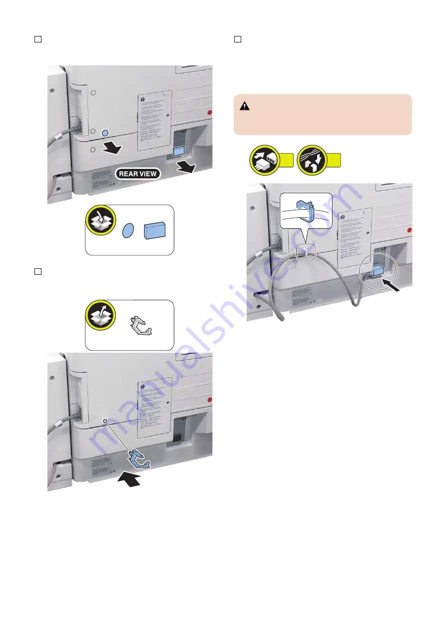
5. Remove the face seal and the connector cover.
6. Attach the wire saddle.
7. Connect the lattice connector to the host machine
and then fix the harness with the wire saddle.
• 1 Connector
• 1 Wire Saddle
CAUTION:
Check that the main power switch is OFF and the
power plug is disconnected from the outlet.
1x
1x
6. Installation
86
Summary of Contents for Paper Deck Unit-F1
Page 13: ... Rear 1 2 No Name 1 Rear Cover 2 Right Cover 1 Product Overview 7 ...
Page 17: ...Technology 2 Basic Configuration 12 Controls 16 ...
Page 25: ...Few PS6 PS11 PS5 OFF ON ON Lifter Full PS6 PS11 PS5 ON ON ON Lifter 2 Technology 19 ...
Page 29: ...Periodical Service 3 List of Work for Scheduled Servicing 24 ...
Page 33: ...Parts List External Covers 1 2 3 4 5 4 Disassembly Assembly 27 ...
Page 53: ...2 Remove the Deck Pickup Release Solenoid 1 2 Screws 2 2x 1 2 4 Disassembly Assembly 47 ...
Page 67: ...Adjustment 5 Adjustment 62 Actions when Replacing the Parts 63 Other Adjustment 72 ...
Page 73: ...8 Fasten the 2 screws 1 on the left loosened at procedure 2x 1 5 Adjustment 67 ...
Page 75: ...10 Fasten the 2 screws on the right loosened at procedure 2x 1 5 Adjustment 69 ...
Page 110: ...APPENDICES Service Tools 105 General Circuit Diagram 106 ...


