


4
4
4-115
4-115
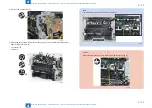
Disassembly/Assembly > Laser Exposure System > Removing the Laser Scanner Unit Duplex models (MF4580dn/MF4570dn/MF4550d/MF4553d/MF4554d/D550/D520)
Disassembly/Assembly > Laser Exposure System > Removing the Laser Scanner Unit Duplex models (MF4580dn/MF4570dn/MF4550d/MF4553d/MF4554d/D550/D520)
Laser Exposure System
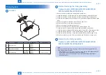
Location
[1]
[2]
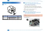
No.
Name
Service Parts No.
Reference
[1] Laser Scanner Unit
FM4-6894 MF4580dn/MF4570dn/MF4550d/
MF4553d/MF4554d/D550/D520
FM4-6929 MF4450/MF4452/MF4453/MF4430/
MF4420n/MF4410/MF4412
[2] Laser Scanner Motor -
-
-
F-4-286
T-4-47
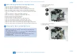
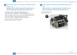
Before Removing the Laser Scanner Unit
Duplex models (MF4580dn/MF4570dn/MF4550d/
MF4553d/MF4554d/D550/D520)
1) Remove the left cover. (Duplex models) (Refer to page 4-31)
2-1) Remove the DADF unit and reader unit. (models with DADF) (Refer to page 4-40)
2-2) Remove the SADF unit and reader unit. (models with SADF) (Refer to page 4-53)
2-3) Remove the copyboard cover and reader unit. (models with copyboard) (Refer to page
3) Remove the right cover. (Duplex models) (Refer to page 4-33)
4) Remove the front cover unit. (Refer to page 4-35)
5) Remove the upper cover. (Refer to page 4-35)
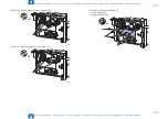
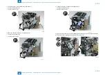
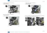
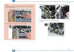
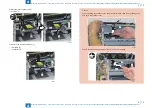
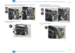
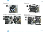
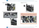
Removing the Laser Scanner Unit
Duplex models (MF4580dn/MF4570dn/MF4550d/
MF4553d/MF4554d/D550/D520)
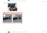
Caution:
Do not disassemble the laser scanner unit because adjustment is required.
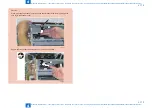
1) Remove the scanner cover [1].
• 2 screws (black TP) [2]
[1]
[2]
x2
F-4-287
Summary of Contents for MF4500 Series
Page 222: ...5 5 Adjustment Adjustment Mechanical Adjustment ...
Page 224: ...6 6 Trouble Shooting Trouble Shooting Test Print Trouble Shooting Items Version Upgrade ...
Page 230: ...7 7 Error Codes Error Codes Overview Error Codes ...
Page 234: ...8 8 Service Mode Service Mode Overview COPIER FEEDER FAX TESTMODE ...
Page 251: ... Service Tools Solvent Oil List General Circuit Diagram General Timing Chart Appendix ...


