Part 2: Repair Information
2-4
3. SERVICE (MECHANICAL DISASSEMBLIES)
Mechanical disassemble should be made following procedures in numerical order.
Following steps show the basic procedures, therefore unnecessary step may be
ignored.
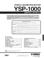
3.1 Cabinet Top and Control Panel Removal
1. Remove 4 screws
A
to take the Cabinet
Top Ass'y upward off.
3.2 Main Board Removal
1. Remove 8 screws to take the Main Board upward off.
CAUTION
The parts and screws should be placed exactly the same position as
the original otherwise it may cause loss of performance and product
safety.
Fig. 2-6
Fig. 2-5
A
A
A
A
Cabinet top
Main Board
Summary of Contents for LV-7355J
Page 9: ...Part 1 General Information ...
Page 22: ...Part 2 Repair Information ...
Page 43: ...Part 3 Adjustment ...
Page 65: ...Part 4 Troubleshooting ...
Page 82: ...Part 4 Troubleshooting 4 17 BA7078AF Selector IC6241 CXA2101AQ RGB Matrix IC4101 ...
Page 85: ...Part 4 Troubleshooting 4 20 ML60851 USB I F IC9801 M62393 D A IC2571 ...
Page 86: ...Part 4 Troubleshooting 4 21 TB1274AF Video Decoder IC1101 TA1318N AFC Detector IC6171 ...
Page 88: ...Part 5 Parts Catalog ...
Page 89: ......
Page 107: ...Part 6 Electrical Diagrams ...
Page 117: ......