background image

 6

I - 3

Completely blank

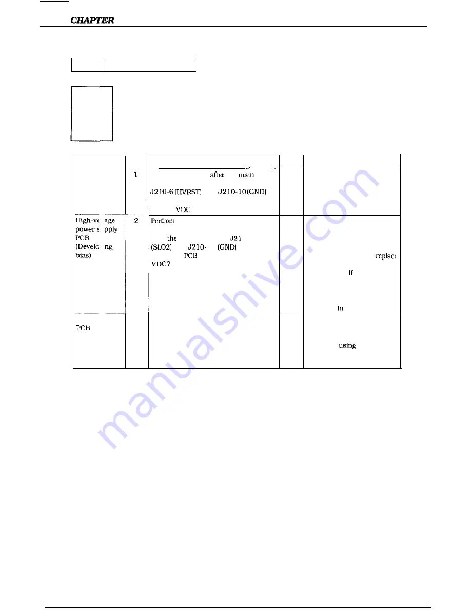
Possible cause Step

Check

Result

Procedure

DC controller 

About one second 

 the 

NO

Replace the DC controller

PCB

motor starts. does the voltage between

PCB.


 and 


on the DC controller PCB change from

about 5 

 to 0 V?

High-voltage

2


 a test print. About five

Y E S

Check whether the high-

power supply

seconds after the main motor starts,

voltage contact Is making

PCB

does   voltage between     O-9

good contact with the

[Developing

 and     10 

 on the DC

developing bias contact of

bias)

controller 

 become about 0.76

the cartridge. If it is, 

the high-voltage power
supply PCB.   the problem

persists after replacing the

PCB, check by using the

laser malfunction diagnosis

flowchart   Section 111 C.

DC controller

NO

Replace the DC controller
PCB. If the problem persist:

after replacing the PCB,
check by 

 the laser

malfunction diagnosis

flowchart in Section III C.

6-18

Summary of Contents for LBP-860

Page 1: ...LBP 860 SERVICE MANUAL Canon ...

Page 2: ...r 3 The Mechanical System Explanation of mechanical operation disassembly reassembly and adjustment procedures Chapter 4 lnstallatlon Kequirements for a suitable location installation procedures plus the storage and handling of EP E cartridges Chapter 5 Mainlmanre and Servicing Parts replacement schedule tools lubricants and solvents Chapter 6 Troubleshooting Heferenrr values and adjustments troub...

Page 3: ... 2 29 D Fixing and Delivery Unit 2 30 E Paper Jam Detection 2 33 V OVERALL CONTROL SYSTEM 2 35 Outline 2 35 B Operation 2 36 C Video Controller PCB 2 37 D Control Panel 2 40 E Self test 2 41 F Status Error Message 2 42 VI POWER SUPPLIES 2 55 Outline 2 56 B Protective System 2 55 VII ENVELOPE FEEDER 2 56 A Outline of the Electrical System 2 56 B Pick up Feed System 2 57 C Paper Jam Detection 2 59 V...

Page 4: ...uggestions 4 7 CHAPTER 5 MAINTENANCE AND SERVICING I PARTS REPLACEMENT A Standard Tools 5 2 SCHEDULE 5 1 B Special Tools 6 3 II EXPECTED SERVICE LIVES V LIST OF LUBRICANTS OF CONSUMABLES 5 1 CLEANERS 5 4 III PERIODIC SERVICE VI SERVICE CHECKPOINTS 5 5 SCHEDULE 5 l VII MAINTENANCE BY IV LISTS OF TOOL6 5 2 CUSTOMER 5 7 CHAPTER 6 TROUBLESHOOTING I INTRODUCTION 6 l A Initial Check 6 l B Basic Procedur...

Page 5: ...rs 6 50 B High voltage Power D PC Boards 6 52 Supply PCB 6 57 E Connectors 6 54 C Pick up Motor Driver PCB 6 58 D Paper Feeder Driver PCB 6 58 APPENDIX I GENERAL TIMING CHART A l VI SENSOR CIRCUIT A l 1 II LIST OF SIGNAL6 A 3 VII PAPER FEEDER DRIVER A 12 HI GENERAL CIRCUIT A 5 VIII ENVELOPE FEEDER DFUVER A 13 Iv DC CONTROLLER A 7 IX VIDEO CONTROLLER A 14 V PICK UP MOTOR DRIVER A 9 X EXPANSION ROM ...

Page 6: ...CHAPTER 1 GENERAL DESCRIPTION I FEATURE3 l l II SF ECIFICATIONS a l 2 III ASAFETY INFORMATION 1 7 IV PARTS OF THE PRINTER 1 S V OPERATION 1 12 ...

Page 7: ...ller system considerably reduces the ozone product d by the charging system and the roller transfer system makes paper feeding more slable 5 Space saving front loading for paper feed Front loading is used to make it easier to load paper This along with the built in mulli purpose tray reduces the size of the printer and the space it takes up 6 Four paper feed methods with various options Four way p...

Page 8: ...rnt dry toner l rvclop w l lbner projection dcvclopmrnt I 1mrr supply Included in replaceabk EP E cartridge The r ridge ran be used to prin about 6 000 purges of A4 Letler sxe paper The average print coverage is II 4 m agc dot ralio with the print density setting in the middle I apf r fwd Multi purpose tray feed Cassrtk feed Two cassetles ran be used when the paper feeder IS insla1led l I I U Sfil...

Page 9: ...5 Legal Letler or Executive Canon approved paper 60 g ml to 90 g m Up lo 10 mm stack height about 100 shrels of80 g m paper A4 Letter liniwrsal Lc l Letter A4 Execuliw B5 IJp to 25 mm stark height aboul 250 sheets of 80 g m paper Up lo 25 mm stack height about 250 sheets of 80 g m2 paper Enwlopr ferdrr and paper leeder C Others Noise levrl DECLARED NOISE EMISSIONS in awordanrr with IS0 9296 L imrn...

Page 10: ...DL Monarch C5 B5 recommended envelope v lol size Envelopes from 90mm X 189mm to 178mm X 254mm i lpx ilv Up to 55 mm stark height about 75 envelopes I 0wer supply DC24V SuppIled by the printer Dimensions 306 5 X 293 X 127 9 mm width X depth X height Wright About 2 6 kri F Paper feeder Paper Feeder Unit PF 4s PF 4L Casseile specifications Power supply Dimensions Wciehl EP E Cassette 500 Universal S ...

Page 11: ...ortional Proportional Proportional PrOpOrtiOIlal Proportional Proportional Proportional Proportional Proporliondl Proportional Proportional Proportional ProportIonal Proportional ProportIonal Proportional Proportional ProportIonal ProportIonal Proportional Proportional Proportionai ProportIonal Proportlonai Proportional PrOpOltIO 3i ProportIonal Proportional I Stroke Weight Medium Bold Medium Bold...

Page 12: ... d 1 6 6 7 8 5 Fixed 1 6 6 7 8 5 Fixed 1 6 6 7 8 5 Medium Medium Medium Medium Medium Medium Medium Medium Medium Medium T I I I I 1056 Linr I rintcr I EGAL Fixed 16 671 8 5 Medium I 5mm f B o t t o m ff sctlve printing area Image quality is guaranteed in this area Right t Feed out dIrection Figure l l Style Orientation Upright Landscape Upright Portrait Upright Portrait Upright Portrait Upright P...

Page 13: ...canner unit emits invisible lasrr beam Never disassemble the unit lhc reflected bram although invisible ran possibly damage your eyes The unit rannot be adjusted in the field The following label is altached to the cover of lhe unit Figure 1 2 1 7 ...

Page 14: ...ce down tray 3 Right rover 4 Control panel 5 Font card slot 6 Power switch 7 Cassette 8 Multi purpose tray 9 Test print switch 10 Delivery cover 11 Power receptacle 12 Parallel interface connector 13 Serial interface connector 14 Cleaning brush 15 Paperaccessdoor Figure 1 5 1 8 ...

Page 15: ...2 Paper feeder 1 Paper feeder 2 Cassette 500 sheets can be placed Figure 1 6 3 Envelope feeder Figure l 7 1 Envelope side guide 2 Exlension tray 3 Weight 1 9 ...

Page 16: ...ntrol panel 5 Multi purpose tray 6 Cassette 7 Mulli purpose tray pick up roller 8 Separation pad Figure 1 s 9 Oblique rollers 10 Cassette pick up roller 11 Developing cylinder 12 Transfer charging roller 13 Photosensitive drum 14 Primary charging roller 15 Upper fixing roller 16 Lower fixing roller l 10 ...

Page 17: ...CHAPTER 1 3 Envelope feeder Figure 1 9 l 11 ...

Page 18: ...R Figure l 10 The operator panel consists of the message menu display window eight indicator lights and sewn menu and operation keys 1 Message Menu Display Window The message menu display window can display as many as 16 characters It displays menu items you can select and messages that describe lhe status of lhe printer and error conditions This chapter describes the menu items you can display in...

Page 19: ...is ready to print An error or attendance message appears in the display The printer is receiving data An error has occurred and printing is disabled An error or attendance message appears in the display No error has occurred Print data is currently stored in the printer s buffer No buffered data is in the printer The printer is ready to accept and print data from the computer on line status The pr...

Page 20: ...shing The optional Envelope Feeder is the input source The optional Envelope Feeder is selected but does not contain envelopes The multi purpose tray is the input source The multi purpose tray is selected but does not contain paper The paper cassette tray is the input source The paper cassette tray is selected but does not contain paper On The optional Paper Feeder Unit is the input source Flashin...

Page 21: ...y is a full page but your software does not send a command to print it you can press ON LINE to set the printer off line and then press FORM FEED to print the last page Keep in mind that complex pages may take several minutes to process Make sure the READY indicator light has stopped flashing before you press FORM FEED lo print the last page The printer must be off line before yoou press FORM FEED...

Page 22: ...us menus and select the available menu items This section briefly describes each key See the Operator Panel Menus section for information about accessing and selecting menu items 4XENU key The MENlJ key cycles through the PCI PRINT MENU and the PCL CONFIG MENU The printer must be off line when you press the MENU key You use the and keys to step through all available choices for a particular menu i...

Page 23: ...nu are marked with an asterisk but do not become active until the printer detects a job boundary or you reset the prinler W Press CONTINUE to set the printer off line withoul performing a reset Need to verify all of this 1 17 ...

Page 24: ... item you want to change 4 When the item you want Co change appears in the display window press or to step through the available choices 5 When the selection appears in the display window press ENTER to save it as the default setting An asterisk appears next to your selection in the display window 6 Press ON LINE to se1 the printer on line 2 Confirming Your Menu Selections There are two ways you r...

Page 25: ...rint job n Permanent default setlings are those you set through the operator panel These selections remain in effect even when you turn off the printer or send a different request through your application You can restore the factory default settings by performing a cold reset To perform a cold reset press and hold the ON LINE key while you turn on the printer The printer displays the message COLD ...

Page 26: ...If you have installed a font cartridge with a default mark the default marked font overrides the factory default font The cartridge default font appears in the PCL PRINT MENU until you selecl a different deCault through the operator panel or your software application you remove the cartridge or insert a different cartridge when the default number is 0 The symbol set for the PCL PRINT MENU is not c...

Page 27: ...MPT 1 OWER ENV Selects the paper size loaded in the multi purpose tray You can selerl LEKITEK 8 5 x 11 inrhrs LEGAL 8 5 x 14 inches EXEC 7 5 x 10 5 inches A4 2 10 x 297 mm COMlO 4 125 x 9 5 inches MONARC 3 875 x 9 5 inches r k llOx220mm H5 182 x 257 mm C5 162 x 219 mm Selects the image size al which the printer formats the page unless a software command overrides it You ran select LMTER 8 5 x 11 i...

Page 28: ...da lgerous if the user presses the key loo long it erases the data in the buffer To override a manual feed request press the CONTINUE key Selects the symbol set see the following lisl The IBl 860 provides 40 symbol sets you can choose A symbol set is a unique grouping of all the available characters in a fonl This listing shows the internal symbol sets you can select from the operator panel Scalab...

Page 29: ...mains in the display until you correct lhe problem tell the printer to continue or both Selecls thr prinlcr interface You can select AUTO Allows the printer to determine the interface port which can lx either parallel or serial The printer displays the communications options described in the next section PAKALLEL Selects the parallel interface only The printer skips to the KES menu option SEKIAL S...

Page 30: ...xpect to use most often Makr sure you have sufficient memory installed for the option you select The figures shown here include 2MB of internal memory You can select OFF requires minimum inslalled memory of 2MH for 300 and 600 dpi LTR requires 2MB for 300 dpi 6MB for 600 dpi 124 requires 2MB for 300 dpi 6MB for 600 dpi LGL requires 3MB for 300 dpi 6MB for 600 dpi t rint density is a measure of the...

Page 31: ...ction correctly when DATA BITS 7 You can select 8 or 7 PARITY NONE Determines whether parity checking is enabled Setting PARITY to EVEN or ODD allows parity checking for some types of data transmission errors When parity checking is enabled the printer will display the message 40 ERROR when it detects a parity error The host computer and the printer must use the same parity setting You can select ...

Page 32: ...d final Self Test Standard Menu Selections Shows standard menu selections such as Printing Menu and PCL Menu and menu options such as copies and MP tray in the order they appear in the control panel display l 2 6 RAM Size Shows the total amount of installed printer memory including added optional memory The LBP 860 comes with 2MB of installed memory If you install optional memory you can use a sel...

Page 33: ... key for approximately five seconds The printer displays the FONT I IIINTOUT message 3 When the Font List is complete press ON LINE to set the printer on line The PCL Font Lisl shows ihe typeface and bitmapped fonts currently available in your printer both internal and oplional for PCL print jobs I he elements of the PCL Font List are as follows Figure 1 16 l 27 ...

Page 34: ...CIIAPTER 1 l 28 ...

Page 35: ...CHAPTER 1 l 29 ...

Page 36: ...ch for example 12 00 h Escape Sequence a PCL command is used to select the designated font Fill in Pitch or Point and Symbol Set in the boxes as required Font is the number you use to select internal cartridge or downloaded soft fonts from the control panel The letter preceding the font number shows the source of the font I is Internal C is Cartridges and S is Permanent Soft Font Font IO is lhe nu...

Page 37: ...t A signal thal is L or has a slash in front of its name is active at ground level and inactive at the supply voltage level There is a microcomputer in this printer But as the internal operation of the microcomputer cannot be checked an explanation of the operation of the microcomputer has been left out As it is assumed that no repair will he made to customer circuit boards the explanation of boar...

Page 38: ...tem To external device computer etc r 3 _ _ _ _ _ _ _ _ _ _ _ _ _ _ _ _ SYSTEM INTERFACE I I 3 I I I I ______ _ 4 __ ____ l _________ d 1 O V E R A L L C O N T R O L S Y S T E M __ __1 I I C controller PCB I I I I Scanning mirror I I I I iI I I k l I __ r__ _ __ __ _ _ I I I 8 Envelope feeder optional II I Cassette i _ _ _ _ __ _ _ _ SYSTEM I ___ _ _______________________ _ Figure 2 1 2 1 ...

Page 39: ...printer goes into standby the microprocessor outputs signals to drive the laser diode motors and solenoids in response to print commands and image data from the exlernal device EXtemal device Video controller PCB DC controller PCB High voltage power supply Pick up motor drwer PCB Sensorslmotorsl solenoids Low voltage power supply b Fixmg roller heater Main swtch F i g u r e 2 2 2 2 ...

Page 40: ...55 c 24VA _______ SW603 SW604 SW605 SW602 lol L z l SW601 EP cartrtdge High voltage power Supply PCB I J74j 2_J_ j O_ I______L_ _ Co necior PCB Figure 2 3 5v DC controller PCB b SNS H when the delivery paper sensor J detects paper or when the delivery caver IS open I L when paper IS detected 2 Y when Q W IS detected 3 H when paper IS detected 4 Y when paper IS detected TJT SLOl OUTPUT SERIAL LINE ...

Page 41: ...ional to the Intensity 01 APCCUT the laser beam IS input The analog signal is output to adjust ir the intensity of the laser beam 27 BDI BD input signal pulse e5V _t 4 t24VB f 5v _f TVIN HVRST I NOUT SLl2 SLO2 IMRDY I IMON z 24VB 2 Figure 2 4 24VA f ISCNON ISCNRDY Scanner motor reference clock signal r to drive the scanner motor L when the scanner motor reaches the prescribed speed High voltage mo...

Page 42: ... 24VA I I I I I I I I I _ I I sensor PC6 ______ IFSRD RLD THOUT FAND FLOCK Y 7 7 SLOl SLll 5v _t 24VB _ YIT 24VA i DC COntrOller PC6 L to swtch the fixing roller heater ON L to deenerg ze the relay OFF and cut power to the fixing roller heater Output the thermistor voltage value H to run at high speed L to r at low speed L when the exhaust fan operates normally OUTPUT SERIAL LINE 1 INPUT SERIAL LI...

Page 43: ...r o r t h e pow r fixing roller so that the swltohed OFF fixing roller will no1 be deformed INTH After Ihc PKNT signal has been To stabilize the sensitivity of INl lIAI input front the video controller the drum in preparation for lIO I ATlONS until thr wanner motor beconws printing and to clean the ptviod ready about ti seconds transfer charging roller PRINT From the end of lhe INTH period To form...

Page 44: ... beam to the DC controller as the AUTOMATIC POWER CONTROL INPUT CHAPTERS The DC controller controls the APCOU I signal to set the APCIN signal to the specified value to stabilize the intensity of the laser beam Control of laser beam intensity APC control The modulated laser beam is formed by a collimator lens and a cylindrical lens into a parallel beam that strikes the scanning mirror which is rot...

Page 45: ... scan The photosensitive drum rotates at constant speed while the laser beam scans across it In the time that the beam takes to sweep Video signal Scanning mirror Figure 2 10 The surface of the photosensitive drum is charged to a negative potential by the primary charging roller before printing starts When laser light strikes the photosensitive drum during the horizontal and vertical scans describ...

Page 46: ...NKING signal UBL and is produced by the DC controller The UBL signal is sent to the laser driver as the FORCIBLE LASER ON signal LON to cause it lo switch the laser diode ON when the LON signal is T yl ANKING stgnal n n n Figure Z 11 2 9 ...

Page 47: ...L signals APCOR APCOS from the DA output ports to the analog adder circuit according to the internal data The AF COR and APCOS signals are added to this circuit at a ratio of approximately 8 to 1 and then sent to the laser current setting circuit located in the laser driver as the AUTOMATIC POWER CONTROL OUTPUT signal AF COUT The CPU adjusts the value of the APCOUT signal by changing the APCOR sig...

Page 48: ...CIN Ihe CPlJ continues coarse adjuslment unlil Lhr inpul value of t h e A P C I N signal reaches 70 of the Larget value stored in Lhe CPU The CPU then does fine adjustment with the APCOS signal and ends the initial APC when the inpul value of the APCIN signal has become almost equal Lo the larget value b Between page AE C Between page APC is performed afler inilial APC and when prinling is not bei...

Page 49: ...e non image area during the non unblinking period IC202 makes the VIDEO DATA ENABLE signal ENBL L only when the TOPE and MSK signals are L The laser driver switches the laser ON when the ENBL signal is L and the VDATA signal is L The gate array IC202 generates the UNBLINKING signal UBL according to the BD INPUT signal BDI sent from the BD PCB in the laser scanner unit IC202 sets the UBL signal lo ...

Page 50: ... DRIVE signal SCNON from the DC controller 2 Scanner motor rotation control Figure 2 15 shows the scanner motor control circuit The scanner motor is a 3 phase 8 pole DC brushless motor containing a Hall element and forms a unit along with the scanner driver which controls scanner motor rotation at constant speed When the printer power is switched ON the oscillation frequency of the crystal X202 is...

Page 51: ...eed the CPU sets the SCANNEK MOTOR READY signal SCNRDY to L The CPU notifies a scanner error to the video controller in the following cases a When the SCNRDY signal does not go V within 20 seconds after the scanner motor starting rotation b When the SCNRDY signal goes H for 2 5 seconds after it goes I 2 14 ...

Page 52: ...ler uniformly applies a negative charge to the surface of the photosensitive drum To form the latent image on the photosensitive drum the laser beam modulated by the VDO signal illuminates the photosensitive drum surface The latent image formed on the photosensitive drum is changed to a visible image by the toner on the developing cylinder then transferred to the paper by the transfer charging rol...

Page 53: ...a toner sensor that detects whether there is enough toner or whether a cartridge is installed If the level of toner in the cartridge becomes lower than the prescribed level or if there is no cartridge in the printer the high vollage power supply PCB notifies the DC controller via the serial line 2 16 ...

Page 54: ... outer layer of the drum consists of an organic p h o t o c o n d u c t o r OPC the base is aluminum The printing process can be divided into five major stages 3 Photoconductive layer 4 _ Base Figure 2 18 5 Electrostatic latent image formation staqe Electrostatic latent image formation stage Step 1 Primary charge I Step 2 Scanning exposure Developing stage Step 3 Development Transfer stage Step 4 ...

Page 55: ...ative potential is applied to the photosensitive drum surface The printer uses the charging method that directly charges the drum for the primary charge The primary charging roller consists of conductive rubber In addition to DC bias AC bias is applied to the primary charging roller to keep the potential on the drum surface uniform This DC bias is changed with the developing DC bias This charging ...

Page 56: ... rotation of the cylinder The areas on the drum that were exposed Lo the laser beam have a higher potential are less negative1 than the negatively charged toner particles on the developing cylinder When these areas approach the cylinder the potential difference projects the toner particles onto them This is called toner projection and the latent image on the drum becomes visible Developing cylinde...

Page 57: ...ws Low transfer voltage that is less than half that for corona transfer Less ozone generation The paper is supported by the transfer charging roller and photosensitive drum so feed is more stable Reference If the image on the photosensitive drum is not completely transferred to the paper due to jamming etc the toner may adhere to the transfer charging roller The printer removes the toner from the ...

Page 58: ... grounded via a diode to prevent the negative potential of the upper roller becoming higher than that of the lower roller resulting in the toner being drawn to the lower roller and adhering to the lower roller surface 5 Drum cleaning stage In the transfer stage not all the toner is transferred to the paper Some remains on the photosensitive drum This residual toner is cleaned off in the drum clean...

Page 59: ... volta on I the cylinder When the potential dif ference between Ihe drum surface and the developing i cylinder is reduced the resulting weak electric field combines with the magnelic field to attract toner back from the drum to the cylinder This removes any excessive toner adhering to the drum and improves the contrast of the finished print The drum surface potential is only slightly higher than t...

Page 60: ... ANT GND REF L I Figure 2 29 Principle of operation Primary charging roller voltage generation When the PRNT signal from the video controller becomes I initial rotation slarts the HVT RESET signal HVRST becomes H and the circuit outputs lhe primaxy AC voltage to the primary charging roller When the PRIMARY DC VOLTAGE ON signal is output to this Primary circuit via the serial line lhe high voltage ...

Page 61: ...tage is applied to the lransfer charging roller during appropriate time to move the toner attached to the transfer charging roller to the photosensitive drum and so clean the roller A print bias voltage is applied to the transfer charging roller to transfer the toner on the photosensitive drum to the paper When the PRNT signal from the video controller becomes L initial rotation starts and a negat...

Page 62: ...ing roller to clean it A positive voltage is applied to the transfer charging roller to transfer toner from the surface of the drum to the paper l I Between page IA w e a k p o s i t i v e c h a r g e i s a p p l i e d t o t h e t r a n s f e r c h a r g i n g r o l l e r t o p r e v e n t bias excessive toner from collecting on the drum Fi rc 2 31 2 25 ...

Page 63: ...CHAPTER 2 This page intentionally left blank 2 26 ...

Page 64: ...he video controller sends the VERTICAL SYNC signal after the paper reaches the sensor and the leading edge of the toner image on the photosensitive drum is matched with the leading edge of the paper The image is transferred then the paper is separated from the drum fed to the fixing unit and delivered onto the face down tray 1 1 1 Delivery Aers Pick up motor driver PCS R Photosensitive PS201 Deliv...

Page 65: ...ocessor on the DC controller detects the cassette size and the presence of a cassette Table 2 3 No cassette This printer cannot detect the paper size on the multi purpose tray until the first page has been printed When the universal cassette is used the user sets the cassette size so there may be a setting error The paper size is detected by the multi purpose tray paper end sensor PS701 if paper i...

Page 66: ...01 or the multi purpose tray pick up roller clulch solenoid SL702 activates for 0 3 seconds to rotate each pick up roller The paper is fed by the oblique rollers so that the edge of the paper touches the left side plate lo correct skew The paper stops at the resist paper sensor PS6021 The VERTICAL SYNC signal VSYNC is received about 0 2 seconds after the pick up motor turns the oblique rollers The...

Page 67: ...istance of the thermistor ffH1 decreases and the voltage of the FIXING ROLLER I SURFACE TEMPERATURE signal FSRTH decreases According to the voltage of the FSRTH signal the microprocessor CPU on the DC controller makes lhe FIXING ROLLER HEATER DRIVE signal FSRD H or L to set the upper roller surface temperature to the appropriate value The target temperatures of the upper fixing roller during WAIT ...

Page 68: ...er being turned ON Fixing roller heater broken wire detection If the upper roller temperature does not reach the standby temperature within 200 seconds of the fling roller heater being turned ON Broken wire detection after the fixing unit becomes ready If the upper roller temperature reaches 140 C in the standby state or during printing Thermistor short detection If the voltage of the FIXING ROLLE...

Page 69: ...xing roller heater ON a preset time after power ON after CPU initialization The CPU assumes a fixing unit error when the upper fiing roller does not reach 172 C 187 C for initial warm up within 200 seconds after the fixing healer is turned ON When the upper fixing roller temperature reaches 172OC 187 C for initial warm up temperature control the READY signal f RDY is output to the video controller...

Page 70: ...aper is picked up PRNT v Unft Seconds Cassette pnk up roller clutch SIBY INTRl PRINT 5 solerod SL701 M tray pick up roller clutch solenoid SL702 Pick up command Jam check n Tl I Reglst paper sensor PS602 1 Normal I Main motor Ml I I 1 1 3 76 swonds upper cassclte 2 85 seconds multi purpose tray I2 00 seconds mvrlrrpc f deer Figure 2 38 2 Pick up unit stationary jam The microprocessor detects a pic...

Page 71: ...unit stationary jam Figure 2 40 The slationary jam when the delivery paper sensor detects the sheet of paper within the required time when the paper passes through lhe resist paper sensor PSSOZ Unit Seconds Unit Seconds Reglst xqer sensor PS 602 I Jam check I_ 53 _I I 5 3 I I Delwery paper sensor PS201 Man motor Figure 2 41 5 Pick up unit or delivery unit stationary jam The microprocessor detects ...

Page 72: ... video controller synchronizes the VIDEO signal VDO with the HORIZONTAL SYNC signal BDJ and the VERTICAL SYNC signal VSYNC sent from the DC controller and sends it to the DC controller In response to the VU0 signal the DC controller generates the LASER DRIVE signal VDATA that switches the laser diode ON and OFF and sends it to the laser driver The resulting laser beam is scanned repeatedly across ...

Page 73: ......

Page 74: ...The NS16550A Serial Controller is used as the interface to the Host serial RS232 RS422 port for printer data JlOO serves as the connector for this interface Parallel Port Interface A 256 byte FIFO is used to buffer printer data from the Host parallel port JllO serves as the connector for the parallel port interface The Generic Array Logic device GAL21 controls the transfer of printer data over the...

Page 75: ...e for each connector Connector Use 5130 Engine Interface 5131 Front Panel 5140 External Video J110 Host Parallel Centronics Port JIOO Host Serial Port 5171 External Debug Port 5172 External I O Slot 5120 PCMCIA n Front Panel The control panel contains 10 LEDs one vacuum fluorescent display VFD 7 swilches and a beeper The function of the front panel is to display status and error messages allows th...

Page 76: ...h input is ineffective or an error occurs Video controller PCB Control panel L _ __ FigUre 2 46 2 Operation The LEDs VFD and beeper on the control panel are controlled by signals from the video controller All signals generated by control panel switches are input to the video controller Table 2 4 lists the input and output signals Table 2 5 Pin No Jl 1 51 2 51 3 51 4 J l 5 J l 6 51 7 J l 8 Jl 9 Jl ...

Page 77: ...M The following checks arr made during this iime Check whether an optional RAM SIMM is inslalled checksum check if it is installed Check internal ROM checksum Internal RAM check IOP check SCSI controller check Optional RAM SIMM check Engine check SRAM check 2 3 When the checks end all LEDs are turned off This state lasts for about 3 seconds 2 4 The READY indicator flashes once 2 5 All VFD digits a...

Page 78: ...display while the printer is operating Figure 2 47 shows how messages appear on the Slatus indication display Figure 2 47 If a warning message operator call or error occurs the field number lights or flashes The printer can display messages on the Status indication display in another language by changing the printing environment setting See page l 23 for details 2 42 ...

Page 79: ...ssage JOB REIJECT The Job in which an error occurred is being skipped TESI PRINT A Self Test Is being printed T FONT LIST A font list is being printed SOFT 01 ION A macro or overlay form registration number is being printed OVERLAY PRINT An overlay form is being printed STOP Utility printing stops WARMING UP Warming up RES ZT Reset FORM FEED Form feeding is in progress FORM FEED STOP Form feeding ...

Page 80: ...ll message is displayed the printer stops printing and goes off line After the operator takes the correct action the printer resumes printing Status indication display wnber llrld Message I I Description MeaSUre 11 PAPER OUT 12 I PRINTER OPEN 13 PAPER JAM 14 NO TONER CART paper supply request Load a cassette containing There is no print paper at the selected print paper at the selected paper sourc...

Page 81: ...lace the cartridge then press the ON LJNE key Load the cassette contalng c the paper specified in the message or select the paper source containing the specified paper If the universal cassette is being used change the paper size to the paper size specified in the message load paper then load the cassette again When the ON LINE key is pressed printing resumes In this case the paper in the current ...

Page 82: ...he lower cassette because the upper cassette Is not loaded Operator comment User defined operator call XX xXx is a messa specified by the Display Comment 1 command This command sends the message from the external device Lo the printer Load the upper cassette or select another paper so K 2 2 46 ...

Page 83: ...wever correct image data on one page It cannot be printed printing is not guaranteed even if the resolution is reduced to 300 Advice the customer to add dpi an optional RAM SIMM If this error occors when Legal size is used take one of the following measures Install optional RAM SIMM This guarantees that data is printed with a resolution of 300 dpi Install optlonal RAM SIMMs 4MB or more and set the...

Page 84: ... then download data Work memory overflow The specified function cannot be executed because of insufficient Internal working wnory video controller Translator missing The translator specitied by the command from the external device does not exist or command parameters are not correct MEMORY FULL 1 Drawing working memory overflow Since there are very complicated j graphics on one page they may not b...

Page 85: ...i horizontal lines appear in the plinted printing The page where th i m a g e error occurred is printed The paper siw selector of the universal I Set the paper size selector 01 cassette is not set correclly The paper the universal casselle size in lhr cassette is different 1 correctly Press the ON LINE key to resume printing from the page in which the error occurred I OF OITI REMOVAL Envelope feed...

Page 86: ...rking memory Measure I Turn the power OFF and ON again If the error occurs again advice the customer to add an optional RAM SIMM NF NVR4M FULL Insufficient NVRAM area The specilled translator cannot find enough NVRAM area Note This error occurs only if the optional translator is used CHAPTER 2 Initialtie with the INITIALIZE group on the group setup menu 2 50 ...

Page 87: ...ccurs turn the the printer for 10 minuets power OFF leave the printer for about then turn the power ON 10 minutes then turn the power ON again If the error is again If the power is turned ON again dfsplayed again perform the before 10 minutes is up the printer troubleshooting procedure displays this message and interrupts the described in Section V of power to the fixing unit Lo prevent Chapter 6 ...

Page 88: ... again If the error cannot be signal is output from the DC controller corrected replace the DC to the video controller PCB controller PCB or video controller PCB No VSYNC signal Turn the pow OFF and The VSYNC signal is not oulput within ON again If the err r the prescribed time after the video persists replace the video controller PCB receives the VSWQ controller PCB signal from the DC controller ...

Page 89: ...AM 2 err r i Dala cannot be correctly read from or I written lo the extended RAM SIMM Turn the power OFF and ON again If the error SCSI loopbark crr r i 2Jf f p fn Data cannot be read from or written to 1 a in If the error cannot be the SCSI ronlroller corrected replace the video I controller PCB SCSI IC inlerrupt err r Turn the power OFF and Oh The SCSI controller cannot generate a again If the e...

Page 90: ...on between cannot be corrected replace the DC controller PCB and video the video controller PCB or controller PCB DC controller PCB IVSREQ signal timeout Turn the power OFF and ON The DC controller PCB does not send a again If the error cannot be IVSKEQ signal to the video controller converted replace the DC PCH within the prescribed time after controller PCB the DC controller PCB receives a PRNT ...

Page 91: ...e power supply and 24VB which is cut when the upper cover is opened and the door switch SW601 is turned OFF The block diagram is shown below 13 I i Power supply _ _ _ _ _ _ _ _ _ic i To fixing roller heater Figure 2 48 B Protective System II a short circuit or other fault causes excessive current from the 24 VDC and 5 VDC power supplies the overcurrent protection system automatically shuts off the...

Page 92: ...s a 1st Start command from the DC controller it runs the pick up motor forward for about 1 8 second pauses for 0 1 seconds then runs the motor backward for about 2 3 seconds One envelope is picked up and fed into the printer by the oblique rollers so that its end touches the left side plate to correct skew The envelope stops when it reaches the resist paper sensor PS602 __ _ DC controller PCB _ _ ...

Page 93: ...ction of the black arrow in Figure 2 521 by the movement of the envelope which is driven by the lower separation roller Since the friction between the envelopes is weak when two or more envelopes are fed simultaneously multi feed the rotating force of the lower roller is not strong enough to cause the upper roller to rotate in the same direction as it is rotating The upper roller rotates in the di...

Page 94: ...CHAPTER 2 C Paper Jam Detection Paper jam during pickup or leeding from the envelope feeder is detected in the same way as l or a printer paper jam detection See pa 2 33 fir details 2 59 ...

Page 95: ...and the printer The paper feeder is supplied with 24 VLX from the printer Paper feeder driver Pick up motor dwer pmlter _ DC controller printer Paper feeder pick up motor J852 1 1 I L P i I i i _ ___ __ _ I i I I T i 4 I i Paper leeder pick up roller clutch solenoid Paper feeder paper sensor Paper feeder cassette size sensing switches 4 M o t o r 1 G driver B 24VA STD PS851 SW851 SW852 1851 l J135...

Page 96: ...per feeder pick up roller clutch solenoid X851 for 0 25 seconds then after 0 1 seconds runs the motor forward for about 1 4 seconds The pick up roller runs through one turn and the feed roller is turned at high speed The motor is then run backward for about 1 2 seconds to turn the feed roller and paper is fed into the printer The paper is fed by the oblique rollers so that its end touches the left...

Page 97: ......

Page 98: ...ACAUTION Before servicing the printer disconnect its power cord from the electrical outlet Assembly is the reverse of disassembly unless otherwise specified Note the lengths diameters and locations of screws as you remove them When reassembling the printer be sure to use them in their original locations Do not operate the printer with any parts removed CHAPTER 3 THE MECHANICAL SYSTEM I EXTERNAL5 3...

Page 99: ......

Page 100: ...ver 6 Front rover 6 Figure 3 1 When cleaning inside the printer or inspecting or repairing il remove the appropriate covers and or panels as described below Right cover Open the printer Remove the screw then move the right cover in holding the rear side of the cover and remove it Screw 0 Right cover pigure 3 2 3 1 ...

Page 101: ...2 Open the delivery cover remove the upper cover unit Figure 3 3 31 fbmove the three XTews 3 1 21 Figure 3 5 Left cover Open the multi purpose tray Remove the right cover and then the upper cover unit Release the left cover hook holding the left side plate then open the left cover to the front and remove it Figure 3 4 Nygure 3 6 3 2 ...

Page 102: ... cover 0 Multi purpose tray 5 1 2 3 41 5 6 Multi purpose tray Remove the cassette Remove the upper cover unit Remove the right cover and then the left cover Remove the control panel unit Open the multi purpose tray Pull the side of the front cover slightly outward and l C IllO the mulli purpose tray from the front rover Figure 3 8 7 Remove the lwo screws and then the slay 0 Screws CZ Stay Figure 3...

Page 103: ...haust Fan Exhaust fan Remove the right cover and lhen the upper cover unit Perform step 1 to 5 on page 3 18 and remove the video controller unit Remove the fan cover hook and then fan cover Disconnect the connector and remove the exhaust fan 0 Fan cover 0 Exhaust fan 0 Connector Figure 3 12 Note on reassembly When installing the exhaust fan attach the fan cover hook to the fan 3 4 ...

Page 104: ...ssembly 1 Remove the two screws and then the control panel a I 2 Kemove the two screws Ij screws a Control panel 0 Screws Figure 3 15 Figure 3 13 3 Release the two hooks holding the control panel unit 41 Disconnect the connector from the control panel and remove the control panel 0 Hooks 0 Connector 0 Control panel unit Figure 3 14 3 5 ...

Page 105: ...Ihc main motor by performing slcps I to 3 on this page 1 2 31 Main Motor Removing the main motor from the printer Remove the right cover Perform sieps 1 to 5 on page 3 18 and remove the video controller unit Disconnect the connector remove lhe four screws and remove the main motor 0 Connertor 3 Main motor Figure 3 17 Figure 3 16 3 6 ...

Page 106: ... two screws disconnect the two connectors and pull the paper pick up unit forward and out 1 Srrews 2 Connertors 31 Paper pick up unit Figure 3 19 Note If you replace the paper pick up unit make several test prints and cherk the leading edge registration is 2 0 mm II it is not adjust il See page 6 9 Figure 3 18 2 a 1 Disassembly and reassembly Pick up motor Disconnect the connector remove the two s...

Page 107: ...tion Then take off two claws on the right side and slide off the regisl sensor holder unit lo the left Slide the left end of the regist sensor holder toward the cassette feed roller shaft front in the figure so that it does not touch lhe oblique roller 0 Projection 0 Claws 3 Regist sensor holder unit Figure 3 22 4 Remove the sensors from regist sensor holder unit Regist paper sensor 0 Cassette pap...

Page 108: ...1111 orlt lhr casse lr pick up roller by ils knob C Multi purpose Tray Pick up Roller 1 Removing the multi purpose tray I Open the multi purpose tray 2 Kenmve the inner cover 31 Push the sub pad hold the knob of the multi purpose tray pick up roller and pull out thr roller I Sub pad 3 Mulii purpos lray pick up roller Figure 3 25 3 9 ...

Page 109: ... the separation pad with a flat Paper Delivery Unit Removing the paper delivery unit Remove the upper cover unit Remove the left cover Remove the leaf spring hladr screwdriver II Leaf spring 1 Separation pad Figure 3 26 Figure 3 27 41 Release the two hooks holding the delivery unit and remove the delivery unit by pulling it forward m Paper delivery unit Figure 3 28 3 10 ...

Page 110: ...Note When removing the cable lrom the laser PCB support the PCB with your hand Ihe PCB can be broken easily it flexed 3 Remove the four screws and then the laser scanner unit cD Screws 0 Laser scanner unit Notes 1 Never disassemble the laser scanner unit it cannot be adjust ed in the field 2 When installing the laser scan ner unit engage the laser shutter with the shutter arm 3 II you replace the ...

Page 111: ... The EWE carlridgr mnot be disasscmblrd 1 1 Primary charging roller a Developing unit 6 Protective shield 8 Photosensitive drum a Drum cleaning unit Figure 3 32 a Protective shield The photosensitive drum is protected by a protective shield that prevents exposure to strong light If the drum is exposed to strong light blank areas or black streaks may appear on prints so do not open the protective s...

Page 112: ...the printer Hook the left side of the transfer charging roller shaft with the supplied green cleaning brush and remove the Iran r charging roller 2 Use flannel or some other soft cloth to clean the drum surface Do n o t use lint free paper because it is too hard and will scratch the surface Never use the solvents to clean the drum 3 Finish cleaning as quickly as possible lo avoid exposing the drum...

Page 113: ...w Fixing roller heater 5 Thermoswitch 6 Fixing unit entrance guide 7 Lower fixing roller 2 1 2 Removing the fixing roller Open the delivery cover Remove the two screws lift the fixing unit slightly and pull it forward and out 3 Screws C2 Fixing unit Figure 3 35 Note When you replaced the fixing unit push the metal levers on both sides of the new king unit down Figure 3 34 3 14 ...

Page 114: ... futing cover I Screws 3 Connector 3 Left fixing cover Figure 3 38 Figure 3 36 2 Releas the seven hooks holding the wire rover to thr lixing unit with a Ilat bladr screwdriver Remove the wire C m 4 Remove the screw and then the fixing roller heater lead from the heater wire l O tT 5 Remove the fixing roller heater lead from the connector 0 Wire cover Figure 3 37 0 Screw 0 Lead 0 Connector pigure 3...

Page 115: ... Remove the two screws Release the hook holding the thermoswitch and remove the 1 hermoswitrh unit 1 Screws 2 Hook 0 Thermoswitch unil Figure 3 41 Note on reassembly When installing the thermoswitch unit make sure that the sensing surface of the thermoswitch contacts the surface of the upper fiing roller uniformly If it does not check whether the leaf spring is bent 3 16 ...

Page 116: ...e the hook holding the upper lixing frame with a flat blade screwdriver and remove lhe upp r fixing frame Note for reassembly When installing the thermistor make sure that the sensing surface of the thermistor contacts the surface of the upper fixing roller uniformly If it does not check whether the leaf spring is bent 0 Springs 0 Upper futing frame Figure 3 43 3 17 ...

Page 117: ...connecter cover b 0 Screws Connector cover Figure 3 47 1 Screw 2 Cover 5 Remove the four screws and then the Figure 3 45 3 Disconnect lhe connector If an optional hard disk drive is installed lwo connectors should be 0 Screws Q Video controller unit Ngure 3 48 m Connector To control panel F9 Connector To hard disk drive Ngure 3 46 3 18 ...

Page 118: ... screws and video controller PCB 3 Screws 2 Shield case Figure 3 49 3 II an expansion ROM PCB is installed the PCB should be rcmovcd 41 IT the RAM SIMM is installed the SIMM should be removed 0 Expansion ROM PCB RAM SIMMs 31 Connectors 4 screws G Video controller PCB Figure 3 50 Note for assembly If you removed the expansion ROM PCB or RAM SIMM when you replaced the video controller PCB reinstall ...

Page 119: ... holder and remove the DC controller PCB 0 Connwtors 21 DC controller PCB Figure 3 51 Figure 3 52 Note on reassembly 3 IXsronrmt the eight connectors from the DC controller PCB When installing the DC controller PCB put the bottom of the PCB into lhe PCB holder then align the PCB with the positioning pin Note When you replace Ihe DC cont roller PCB make sure you adjust the leading edge registration...

Page 120: ... PCB I Remove the pick up motor driver PCH by performing steps 1 and 2 on this page 2 Disconnect the three ronrvxAors Figure 3 53 Figure 3 54 3 Kdease lhe three hooks and remove thr cover 0 Hooks 0 Cover Figure 3 56 3 21 ...

Page 121: ...e screws and then the connertor cover Figure 3 56 iI 1 Screws c2 Connector cover Figure 3 57 3 Remove the two screws disconnect the two ronnectors remcwe the rod and pull the dower supplv forward and out Q screws 2 Connectors 3 Rod Power supply Figure 3 58 3 22 ...

Page 122: ...oltage Power Supply PCB I l rmovc hr cassellr 2 Stand the prinler on its right side 3 Iiernow Ihr two screw release the Iwo hooks and remove the high voltage c as Ihe the 0 High voltage power supply PCB Figure 3 60 3 23 ...

Page 123: ...Figure 3 6 1 Figure 3 62 c Bottom cover 1 Kemnve the right cover and lel t cover 2 Remove the rour screws and remove the bottom cover Q Screw 0 Bottom cover Figure 3 63 3 24 ...

Page 124: ...ews and remove the pick up motor 0 Screws Q Pick up motor EIgure 3 65 2 Removing the envelope feeder drive PCB 1 Remove the right left and bottom covers 2 Disconnect Ihe two connectors and remove the screw 0 Connectors Q Screw Figure 3 66 3 Remove the sensor lever then remove the envelope feeder driver PCB m 0 Sensor lever 0 Envelope feeder driver PCB Figure 3 67 3 25 ...

Page 125: ...crew holding the ground wire Release the right and left snaps with a flat blade screwdriver then remove the upper cover 0 E rings Pick up rollers 2 Bushings Figure 3 68 Figure 3 69 3 Kemow Ihe gear from the pick up roller shaft Release the pick up mller hooks holding the shaft and remove the pick up rollers 3 Remove the two E rings and two bushings then remove the lower separation roller shaft Rem...

Page 126: ... 71 Note 1 Remove the separation guide and the upper cover as a unit If the separation guide must be removed separately adjust the posilion 01 thr guide after reinslallalion See page 6 8 2 When assembling install the oldham joint as shown below Note 3 When assembling check the separation roller pressure spring has been installed correctly 0 Separation roller pressure spring Figure 3 73 3 27 ...

Page 127: ...elease the two claws and remove the ZZ Connectors 0 Cable tie Screws Drive unit 0 Claws G Front rover Figure 3 76 Figure 3 74 2 Remove the screw release the two claws and open the PCB cover 0 Screw 0 PCB cover 0 Claws Figure 3 76 3 Disconnect the two connectors and remove the cable tie 3 28 ...

Page 128: ... Screws QI Pick up motor Removing the paper feeder driver PCB Remove the screw release the two claws and open lhe PCB cover See Fig 3 75 Disconnect the three connectors and remove the cable tie Release the claw holding the PCB then lift the paper feeder driver PCB 0 Claw I Paper feeder driver PCB Figure 3 79 4 Removing the paper feeder pick up roller I Pull out the pick up roller by its knob figur...

Page 129: ......

Page 130: ... it must be installed correctly The service engineer must choose a suitable location install the printer according to the proper procedures then fully check the printer before It Is used The requires a thorough understanding of the printer II I CHOOSING A LOCATION 4 1 II UNPACKING AND MSTALLATION 4 2 III STORAGE AND HANDLING GF CARTRIDGES 4 6 ...

Page 131: ...ve curtains keep to the sun off Near magnets or equipment that produces a magnetic field Where there is vibration Where it is dusty Near flames or water 2 Operatinn conditions J Installation apace There must be an enough space around the Flat level supporting surface Ambient temperature of 10 lo 325 C Humidity of 20 to 80 KH No condensation Good ventilation printer to operate it See Figure 4 l The...

Page 132: ...e the following the documentation out l Power cord l Manual l Cartridge Lift off the Styrofoam pads right and left then lift the printer i out 4 Take the printer out of its plastic bag Peel off the tape holding the vartous components 5 Take the cassette out and remove tie lifting plate retainer from the cassette 6 Open the printer and remove the tape and the spacer inside the printer 7 Remove the ...

Page 133: ...CHAPTERS Cartridge box Lower Styrofoam pad Lower Styrofoam pad Spacer Protective sheet 4 3 ...

Page 134: ...idge out Take the cartridge out of its aluminum bag i 2 Hold the cartridge as shown in See Figure 4 6 Fig 4 6 and slowly rock it 45 rach way live or six times to distribute thr lonrr evenly 4 Oprn the printer hold the Slowly insert it until it is rartridge in both hands and securely seated at each install it in the printer 5 Close the printer Figure 4 4 4 4 ...

Page 135: ...ord in and Check lhat the density of the stitch the printer ON When the test print is right READY indlratnr slops Ilashing the printrr is standing by Press Ihr ON LINE key to put the printer off lirw then press the TEST FONT key to run ofT a test p r i n t 3 For safety keep the area around the nter clear I 4 5 ...

Page 136: ... all about correct storage and handling of cartridges 1 1 2 31 4 5 6 7 2 Storage requirements after unsealing Store the cartridge in its aluminum bag Avoid places in the sun or near windows Do not leave a cartridge in a car for a long time as the inside of the car can get extremeiy hot Even if the cartridge is in its box do not put the box in the sun or leave it in a car for a long time Avoid plac...

Page 137: ...to light 3 Keep rartridges away from computer workstation disk drives and floppy disks The magnet in the cartridge can corrupt the video data in the memory of the workstation or the data on disks Figure 4 6 4 Since the photosensitive drum is sensitive to light never expose it to direct sunlight or strong light 1500 lux or more If you do blank spots or black streaks may appear on prints If this doe...

Page 138: ...with its label up 7 Never take a r ridge apart Note If the photosensitive drum gets expost d to normal light of about 1500 lux for about 5 minutes store the rartridgr in a dark place to rewvc Direct sunlighl is 10 000 to 30 000 lux Exposing a drum to light this bright will destroy il 4 8 ...

Page 139: ...NG I PAPERS REPLACEMENT SCHEDULE I S 1 IL EXPECTED SERVICE LIVES OF CONSUMABLBS S 1 III PERIODIC SERVICE SCHEDULE S l IV LISTOFTOOLS a 5 2 V LIST OF LUBRICANTS CLEANERS 6 4 VI SERVICE CEiECKPOINTS I S 5 VII MAINTENANCE BY CUSTOMER 5 7 ...

Page 140: ...l As of January 1994 NO 1 2 3 Parts nan r Multi purpox pick up I Oiler Separation pad Fixing unit Par18 No Qr Y RBl 2127 000 2CQOOO sheets Service life Replace the multi purpose pick up roller and separation pad together 100 l 15v 220 240V RF5 0343 000 2CKNOO sheets RG5 0454 130 2IXK00 sheets RG5 0455 130 200 C00 she RF5 0349 000 1 1 200 000 sheets R131 2126 000 1 200 000 sheets R117 I 143 000 1 2...

Page 141: ...recision flat blade scvsvdriver seL 1 CK 0114 11 Allen wrench set CK 0151 12 File finr CK 0161 13 Allrn hex srrrwdriwr CK 0170 M4 14 Diagonal cutling pliers CK 020 1 15 Nerdlr rmsr pliers CK 0202 16 mrrs CK 0203 Slip joint 17 Relaining nng pliers CK 0205 For external rings 19 30 mm 1N crimprr C K 0 2 1 8 19 Twrcecrs CK 0302 20 Kulrr CK 0303 150mm 21 1 Soldering iron C K 0 3 0 9 1oov 3ow 22 Mallrl ...

Page 142: ...emarks 1 Printer driver D Used for checking the trstw operation of the printer or checking a failure of Ihe lam diode 2 Thickness gauge RYY 0088 2 1 c e A 1 Used for installing the i I 1 separation guide 3 Thicknessgauge 1 QY9 0001 Note Ranks A Each service technician should carry one with him B A group of the service technicians should share one C Each workshop should keep one 5 3 ...

Page 143: ...ly rthyl ketone toner stains l Highly flammable keep away from flame 3 1 Luhrirating oil i IS0 VG 68 oil ESSO Apply between gear il Tool No CK 0451 Febis K68 MOBIL and shaft 500 g can Vactra oil No 2 SHELL l Equivalent oil may be Tonna oil 1 68 used Never apply to the molding or the gear at the molding because it has a bad effect on the molding 4 Lubricating 1 Special metallic soap Apply to gear T...

Page 144: ...g brush Clean eliminator Multi purpose tray pick up roller Point Tool solvent 1 Remarks Multi Damp cloth or Clean Separation pad Point Tool solvent Remarks Separation 1 Dry cloth I CL7 pad Transfer charging roller Point Tool solvent Remarks Transfer Lint free paper Clean the roller only if it is very charging dirty Do not touch the roller roller and try not Lo have any solvents or 011 on your hand...

Page 145: ...atic charge rliminator Transfer guide area Customer maintenance Rock the cartridge to redistribute toner If necessary r w it When replacing the cartridge clean the static charge eliminator with the green cleaning brush in the printer When replacing the rartndge clean the transfer guide area wit1 the soft dry cloth 5 7 ...

Page 146: ...AL TOOL I 6 4 III MEASUREMENT AND ADJUS NT 6 7 IV IMAGE DEFECTS 6 14 V TROUBLESHOOTING MALFUNCTIONS 6 28 VI PAPER TRANSPORT TROUBLRSHOOTING 6 42 VII LOCATION OF ELECTRICAL PARTS FUNCTION 6 46 VIII VARIABLE RESISTOR6 LEDS TEST PINS JUMPERS AND SWITCHES ON PC BOARDS 6 56 ...

Page 147: ...d in the printer If the message appears the amount of toner is insufficient prepare a new cartridge If blank spots appear on prints the toner is unevenly distributed in the cartridge Take the cartridge out and slowly rock it from side to side to distribute the toner evenly as described in Section 111 of Chapter 4 4 Other points During winter if the printer is brought into a warm room from a cold o...

Page 148: ...s perform the initial check then follow the basic procedure below 1 If the printer malfunctions read section V on troubleshooting 2 If an image defect occurs determine the type of image defect from the list of image defect samples on page 6 14 and correct the defect 6 2 ...

Page 149: ...tage is not available at the outlet NO Push the power plugs in firmly To find the possible causes parts likely to be defective of a particular fault refer to the item marked IPossible cause in the table In the case of No AC Power in the above table it is possible that the line voltage or power plug is defective 6 To repair or check the faull follow the numbers in the Step column and answer the que...

Page 150: ... PRINT Permits the printer to print the pattern specified by VIDEO SELECT VIDEO SELECT Selects the test pattern to be printed black hnage vertical lines horizontal lines or a white image PAPER FEED METHOD SELECT Picks up the paper or the envelope from one of the following l Upper cassette Multi purpose tray l Lower casselte cassette feeder l Envelope feeder READY CONTROL ON places the printer in a...

Page 151: ...he regist paper sensor MI TRAY END SENS LED Lights when paper is at the MP tray paper end sensor DELIVERY SENSOR LED Lights when paper is at the paper delivery sensor TONER SENSOR LED Lights when there is toner in the cartridge when the primary AC bias is being output PAPER SIZE LED Indicates the paper size of the cassette in the paper pick up unit specified by the PAPER FEED METHOD SELECT switch ...

Page 152: ...connector 5135 for the paper feeder or the connector J 136 for the envelope feeder Set the printer power switch to ON When the printer goes into stand by operate the tester to perform the check Note If your body is electrically charged when you operate the printer driver tester printer misoperation or malfunction may occur So be sure to touch a metal part of the printer with your hand Lo discharge...

Page 153: ...t does not allow adjustment of the pressure nip width If the nip width nip width is set incorrectly a fixing problem may occur 1 21 3 1 4 5 Either take along one or two A4 lelter size all black copies made on copier or make such a copy using a copier at the customer site Put the all black copy on the multi purpose lray Press the TEST FONT key When the leading edge of the print emerges at the face ...

Page 154: ...ide or replaced a bent separation guide adjust the gap as follows Install the separation guide at the position 1 5mm away from the lower separation roller Adjust its position by inserting the thickness gauges lmm and 0 5mm i n t o t h e g a p b e t w e e n t h e separation guide and the lower separation guide cCross sectlonal view of the envelope feeder Separation guide Thickness gauges Thickness ...

Page 155: ... the DC controller PCB 2 Set VR202 PCB on the DC controller to to then place sheets in the cassette Press the TEST PRINT switch and obtain several test prints Leadingedgeofpaper Figure 6 6 3 Measure the distance a from the leading edge of each sheet to the pattern See Figure 6 6 Take the average of the measured distances 4 Adjust VR202 so that the value obtained in step 3 is 2 0 mm according to Ta...

Page 156: ...CHAPTER 6 J201 IWO2 IC201 L l J212 TB201 J211 J210 Figure 6 7 6 1 0 ...

Page 157: ...CHAPTER 6 This page intentionally left blank 6 11 ...

Page 158: ...ter Driver tester b Digital multimeter l l Meter c EI E cartridge Cartridge 2 The printer driver tester switches marked with x can be set to any position 3 The voltage must be measured three times and the average taken Before usinz the flowchart Set the inter power switch to OFF and remove the cartridge Attach the driver tester connector to the envelope feeder connector 51361 Set the driver tester...

Page 159: ...gainst the following connector pins on the DC controller PCS connector pins on the DC controller PCB f r V D COM DC controller J206 6 APCOUT J206 7 GND _M V D DC controller J206 5 APCIN COM 5206 7 GND Tp CHECK switch of the driver tester 1 YES Switch the power OFF and laser scanner unit Switch the power OFF and replace the DC End Does the meter indicate 0 95 to CHECK switch of the driver tester Th...

Page 160: ...ular and smudged horizontal bands l 12 Faulty registration l 3 Completely blank l 6 Dtrl on back 01 l 7 Vertical black streaks EY l 10 Blank spots I 1 3 Poor fixing i 1 4 Distortion Figure 6 9 l 4 All black l 8 Irregular and smudged vertical bands l 11 Solid vertical white lines l 15 Missing BD signal 6 14 ...

Page 161: ...S Replace the ptint paper new paper is used Advise the customer of the proper method to store paper r ansfer 5 harging roller Does thr image become darker when YES Replace the roller the transfer charging roller is replaced High vrrllagr power supply PCB transrer voltage DC cnntroller PCB 6 Perform a test print About two YES Check the continuity seconds after the main motor starts between the high...

Page 162: ... good contact with the Developing J21D 10 GND on the DC controller developing bias contact of blasl PCB become about 0 76 VDC the cartridge If it is replarr the high voltage power supply PCB If the problem persists after replacing the PCB check by using the laser malfunction diagnosis flowchart in Section III C DC controller PCB PCB If the problem perslste after replacing the PCB check by using th...

Page 163: ...tact is making 5210 6 HVRSV and 5210 10 GND good contact with the on the DC controller PCB change from primary charging roller of 0 V to about 5 VDC the cartridge If it is replace lhe high voltage power supply PCB If the problem persists after replacing the PCB check by using the laser malfunction diagnosis flowchart in Section 111 C 3c controller PCB NO Replace the DC controller PCB If the proble...

Page 164: ... after the main motor starts voltage contact Is making PCB does the voltage between 52 1 O 9 good contact with the Developing SLO2 and 52 lo 10 GND on the DC developing bias contact of bias controller PCB become about 0 76 the cartridge If it is replace VDC the high voltage power supply PCB If the problem persists after replacing the PCB check by using the laser malfunction diagnosis flowchart tn ...

Page 165: ...s the voltage between 5210 9 SLOZ and 52 lo 10 GNDI on the DC controller PCB become about 0 76 VDC esult fES YES NO Procedure Replace the cartridge Replace the high voltage power supply PCB If the problem persists after replacing the PCB check b using the laser malfunction diagnosis flowchart In section 111 c Replace the DC controller PCB If the problem penistz after replaclng the PCB check by usi...

Page 166: ...dirty roller If it is not charging roller possible to clean Lt replace I 6 1 Dirt on hack of paper Possible cause Step Check Result Procedure Is the transfer charging roller dirty7 YES Clean the roller If it cannot be cleaned replace It ______ Is the entrance guide dirty YES Clean the guide _____ NO Ground the rollers properly Y E S Clean the roller If it is not possible to clean it replace it N O...

Page 167: ...e performed and open the protective Fixing unil shield of the rartridge Are vertical I NO black streaks on the drum Replace the fting unit I 8 Irregular and smudged vertical bands Possible cause 1 Step 1 Check 1 Result Procedure I El E c a r t r i d g e 1 I I Does the print quality improve when I I YES Replace the cartridge the cartridge Is replaced I 6 21 ...

Page 168: ...CIMPTER 6 I 9 Irregular and smudged horizontal bands 1 Check the bands appear at regular intervals Procedure Replace the cartrtdge 6 22 ...

Page 169: ... YES Replace the cartridge the cartridge Is replaced7 High voltage 5 Perform a test print About five seconds YES Check whether the hlgh power supply after the main motor starts does the voltage contact is making I CB voltage between 5210 9 SLOZ and good contact with the Developing J2 1 O 10 GNDI on the DC controller developing bias contact of bias PCB become about 0 76 VDC the cartridge If it is r...

Page 170: ...rface YES Is paper dust adhering to the reflection YES Replace the laser scanner mirror in the laser scanner unit7 unit Is any fore matter such as a hair adhering Lo the laser outlet of the ca F pnnter or the laser Inlet of the Procedure Take out the cartridge rock it as shown in Section III of Chapter 4 to distribute the toner evenly then put it back Replace the cartridge Remove the foreign matte...

Page 171: ...s i b l e cause Steps 1 Check _ _ _ _ __R lti Procedure Number of 1 Is the multi purpose tray or the YES Advise the user not to load sheets cassette overloaded the tray or the cassette with excessive amount of paper the registration is adjusted 6 25 ...

Page 172: ...vertical band Is the lower fming roller dirty Ii the nip width correct YES YES Replace the thermistor YES YES YES NO Procedure Clean the roller If it is not possible to clean replace it Check whether the upper and lower fixing rollers are damwed Clean the roller If it is not possible lo clean it replace it __ Perform a print using the recommended paper If the problem disappears advise the customer...

Page 173: ...e connectors DC controller PCB making good contact 2 Is conneclor J731 on the BD PCB NO Attach the connector making good contact _ Iasrr scanner 3 Check by using the laser malfunction YES Replace the laser scanner unil diagnosis flowrhart In Section II1 C of unit DC controller this chapter NO Replace the DC controller Pen Is the laser scanner unit faulty Pen 6 27 ...

Page 174: ...at the NO Advise the user that the outlet correct line voltage is not available at the outlet Power plug 2 Is the power cord securely plugged NO Push the power plugs in into the printer and the outlet Cirruit 3 _ ________ _ firmly Is the circuit breaker OFF YES Turn the circuit breaker breaker ON If the breaker turns OFF again as soon as the power is switched ON check for a short circuit wiling 4 ...

Page 175: ... the power DC controller PCB and DC DC controller switch ON and measure the voltage load If it is normal replace PCB between the terminals shown in the the DC controller PCB Power supply table below Is the voltage normal Replace the power supply M 3 Status indication display on control panel does not work properly Possible rause Step Check Result Procedure Control panel 1 Does the problem improve ...

Page 176: ... the control panel NO Replace the video controller PCB M 6 Control panel switch malfunction Check Werr switches turned ON OFF according to Section V of Chapter I Procedure Turn ON OFF the switches arcordinF to Section V of Control panel 2 Video conirollPr PCB Does the problem improve when you replace the control panel Chapter YES Replace the control panel NO Replace the video controller PCB 6 30 ...

Page 177: ...er PCB moved does the voltage between DC rontroller connectors J605 6 CRESS and J605 5 IGND on the pick up motor driver PCB change from about 5 VDC to zero NO paper sensor arm is damaged If it is replace it if it is not replace the regist paper sensor Check whether the delivery paper sensor arm is damaged If it is replace it if it is not replace the delivery paper sensor Replace the pick up motor ...

Page 178: ...er loaded correctly 7 NO 8 Connect the printer driver Lester to the printer When paper is put on the multi purpose tray does the MP TRAY LED of the tester light YES Replace the DC controller PCB DC controller PCB Sensor PCB multi purpose tray paper X SOr Paper feeder driver PCB cassette size senstng switch NO NO Replace the sensor PCB 9 Connect the printer driver tester to the printer When the pap...

Page 179: ...am 5 Is the regist paper sensor arm or YES Replace the damaged paper delively paper tensor arm damaged sensor arm Delivery 6 When the delivery papel sensor arm NO Replace the delivery paper paprr sensor is moved does the voltage between sensor connertors 5208 3 I SNS and 5208 2 GNU on the DC controller PCB change from zero to about 5 VDC Pick up motor 7 When the regist paper sensor arm is YES Repl...

Page 180: ...r on the pick up motor driver PCB zero Replace the pick up motor driver PCB when thr upper cover is closed M 10 14 NO TONER CART appears even though a catridge is loaded 1 Possible cause 1 Step 1 Check j Result Procedure I EP E cartridee 1 1 DC controller 2 PCB Hi voltage power supply Is the cartridge loaded properly Turn the printer OFF connect the printer driver tester and turn the power back ON...

Page 181: ...r swKch is turned Replace the high voltage powrr supply ON power supply PCB M 12 Faulty Pick up Motor Sensor PCB Pick up motor _ Pick up molar driver PCB DC controller PCB 1 step 2 3 Check 1 Result Procedure Are the ronneclors J60 1 J602 from connector 5201 on the DC controller PCB to connector J701 on the sensor PCB making good contact Reattach the connectors Are the connectors 5701 and J702 on t...

Page 182: ...6 I9311 lrom connector 5201 on the DC controller PCB Lo connertor 5932 on the envelope feeder driver PCB making good contact Does the problem improve when the envelope feeder is replaced7 Place some envelopes on the envelope feeder and perform a test print by using thr printer driver tester After the prescribed time do the voltages between the following pairs of terminals on the envelope feeder dr...

Page 183: ...otor start running _ Pick up 3 Place some paper in the upper NO Replace the pick up motor motor driver cassette and perform a test print by driver PCB If the problem Pen using the printer driver tester After persists after replacing the DC controller the prescribed lime does the volt PCB replace the DC PCB between connectors J602 A3 1ST controller PCB and J602 A5 ND on the pick up motor driver PCB...

Page 184: ...up motor w art nlnntng Pick up m tor driver PC13 DC antroller PCB 3 1 Place some paper on the multi purpose tray and perform a test print by using the printer driver tester After the prescribed time does Che voltage between connectors J602 A2 MP and J602 A5 GND on the pick up motor driver PCB change from 0 V Lo about 1 3 VDC Replace the pick up motor driver PCB If the problem perslsls after replac...

Page 185: ...tedcr 4 Plarc paper in the lower cassetlr and Replace the paper feeder pick up roller perform a tesl print by using the pick up roller clutch rlutrh solenoid printer driver lesler After the prrscrib d lime does the voltage between connectors 5853 3 PSTD 1 _ __ Paper feeder I and 5853 l 24X on the paper feeder NO Replace the paper feeder driver PCB drlcrr PCR change from 0 V to about driver PCB 24 ...

Page 186: ... replacing the PCB PCB replace the connector PCB M 20 Faulty Exhaust Fan Posstble aw step Check Procedure i Connertor Is ronnector J209 on the DC controller Reattach the connector PCB making good contact Exhaust fan D ouch connector 5211 on the DC Replace the exhaust fan DC conlrotler rolltroller PCB i I Immediately after the power is turned Replace the DC controller PCB ON does the volta z betwee...

Page 187: ...nd switch the power ON Is the voltage between connectors J212 1 FSRD and TBZOl 6 IGND on the IX controller PCB initially about 5 1 VDC and does it change to about 1 5 VDC as the 0xln g roller warms up NO Switch the power ON Is the voltage between ronneclors 5212 2 RJD and TB201 6 GND on the DC controller PCB about 5 VDC YES Replace the power supply Power supply DC controller PCB NO Replace the DC ...

Page 188: ...ser scanner 3 Replace the laser scanner unit between connectors J205 7 JSCNON DC co lroller and 5205 4 GND on the DC Replace the DC controller PCH controller PCB change from about 5 VDC to 0 V M 25 1 5F 54 SERVICE Message 1 Possible rause Slep 1 Check 1 Result 1 Procedure Ar connector 52 11 on the DC NO Reconnect the connectors controller PCB and connector 5131 of the main motor making good contac...

Page 189: ...rough two major sections in the printer 11 the pick up section and 2 1 the fixing and delivery section The following explains how to troubleshoot jams in each of these serlions r A I Pick up section 2 Fixing and delivery section Figure 6 10 6 42 ...

Page 190: ...s e paper tray P i c k u p r o l l e r 7 Dors the pick up roller rotate when Y E S Replace the roller Pick up lailure printing is performed NO Check by following the step in M 16 No Paper Pick up from Multi purpose Tray CWS llP 8 Is the cassette positioned correctly in NO Position the cassette thr printer or the paper feeder correctly P a p e r l o a d e d 9 Is lhe paper touching the cassette NO L...

Page 191: ...in the same manner as for M 18 No Envelope Pick Up from Envelope Feeder T 2 Fixing and delivery section Possible cause Step Check Result Procedure _ Enlrance 1 Is the entrance guide dirty YES Clean the guide guide Is the guide damaged or is there toner onI _ ________ Delivery guide 2 Is the delivery guide dirty YES Clean the guide Is the guide damaged or is there toner on it7 _ _ _ _ _ _ _ _ _ _ _...

Page 192: ...ecommended paper being used NO Advtse the user to only use the recommended paper 2 Does the paper stop becoming YES Advlse the customer on hov wrinkled when new paper is used to store the paper to preven i it becoming damp Pirk up unit 3 Open the printer while a sheet of YES Check the pick up unit paper is passing through the feeder unit after pick up Is the paper Entrance wrinkled at thts point I...

Page 193: ... C HAFTER 6 A Switches Figure 6 11 6 46 ...

Page 194: ...ze sensing switch 1 Upper cassette size sensing switch 2 Upper cassette size sensing stitch 3 Lower cassette size sensing switch 1 paper feeder Lower cassette size sensing switch 2 paper feeder Lower cassette size sensing switch 3 paper feeder 6 47 ...

Page 195: ...CHAPTER 6 B Sensors and Solenoids esgure 6 12 6 48 ...

Page 196: ... senscn cassette papa sensor Regist paper sensor Multi purpose tray paper end sensor Multi puqxse tray paper sensor Paper feeder paper sensor paper feeder Envelope feeder paper sensor envelope feeder Cassette pick up roller clutch solenoid Multi purpose tray pick up roller clutch solenoid Paper feeder pick up roller clutch solenotd paper 1feeder 6 49 ...

Page 197: ...CHAPTER 6 C Motors and Others Figure 6 13 6 50 ...

Page 198: ...photosensltive drum and feed rollers Drives the paper pick up rollers Drives the paper feeder pick up rollers paper feeder Drives the envelope feeder pick up rollers Ienvelope feeder Drives the scanning mirror Exhaust fan Heats the upper fixing roller Thermistor Ttil 1 Detects the upper fLving roller surface temperature 6 51 ...

Page 199: ...D PC Boards Ngwe 6 14 6 52 ...

Page 200: ...r Drives the motors and the solenoids Relays signals between the sensors solenoids motors and pick up motor driver PCB Processes I O between the printer and the external device and various data Conlrols the timing when the video controller unit CPU gives access to the ROM SIMM module mounted on the expantion ROM PCB Drives the paper feeder clutch and the motor paper feeder Drives the envelope feed...

Page 201: ... CHAPTER 6 E Connectors Figure 6 15 6 54 ...

Page 202: ...CHAPTER 6 Figure 6 16 6 55 ...

Page 203: ...recision Do not touch them when servicing Notes 1 Some LEDs receive leakage current during normal operation causing them to glow dimly when they should be OFF 2 Polentiometers that may be adjusted when servicing are marked __ 0 Potentiometers that may not be adjusted when servicing are marked A DC Controller PCB J203 6 11 J204 J202 1 J201 J206 l l13 0 CP202 1 J212 3 I TB20 I J2 IO J2 0 1 5213 P u ...

Page 204: ...CHAPTER 6 B High voltage Power Supply PCB I TB401 TB402 TB403 TB404 0 II VR40 TB406 5401 Plgure 6 18 Table 6 11 m No Function vFC401 For factory use I 6 57 ...

Page 205: ... 0 SW604 0 SW605 0 D Paper Feeder Driver PCB 0 J852 Table 6 12 SW No FUlICtiOn SW60 1 Door sensing stitch SW602 1 Test print switch SW603 sw6o4 Cassette size sensing switch SWfmFi I See page 2 28 I Table 6 13 SW No I Function SW80 1 sw8o2 Cassette size sensing switch See page 2 28 I SW803 c J Fi m 6 20 6 58 ...

Page 206: ...G CHART A l IL LIST OF SIGNALS A 3 DtI GENERAL CIRCUIT A 6 N DC CONTROLLER A 7 PICK UP MOTOR DRIVER A S VI SENSOR CIRCUIT a A 11 VII PAPER FEEDER DRIVER A 12 VIII ENVEL0PE FEEDER DRIVER A 13 IX EXPANSION ROM CIRCUIT ma A 16 I ...

Page 207: ...HART Power switch ON Unit Seconds Operation n STBY INTR 1 PRINT LSTR STBY Exhaust fan FMI 7 Main motor Ml 11 Registpapersensor PS6G2 4k 3 I I I 12 Delivery paper sensor PS201 I I I 13 Primary voltage AC 14 Primary voltage DC 1 I 15 Developing bias AC I _I 1 1 I o 3 _i k 0 32 I I I I A l ...

Page 208: ... DRIVE signal FSRTH FIXING ROLLER SURFACE TEMPERATURE signal HVRST HVT RESET signal LON FORCIBLE LASER ON signal MON MAIN MOTOR DRIVE signal MRDY MAIN MOTOR READY signal PCLK PRINTER CLOCK signal PPRDY PRlNTER POWER READY signal PRNT PRINT signal PSNS DELIVERY PAPER SENSOR signal RDY READY signal RLD RELAY DRIVE signal SCNCLK SCANNER REFERENCE CLOCK signal SCNON SCANNER MOTOR DRIVE signal SCNRDY S...

Page 209: ...APPENDIX Abbreviation NSUlle I VDO VIDEO signal VSREQ VERTICAL SYNC REQUESI signal VSYNC VERTICAL SYNC sinnal A 4 ...

Page 210: ......

Page 211: ......

Page 212: ......

Page 213: ......

Page 214: ......

Page 215: ......

Page 216: ......

Page 217: ......

Page 218: ......

Page 219: ......

Reviews: