5-7
5-7
5
5
Adjustmnet
Adjustmnet
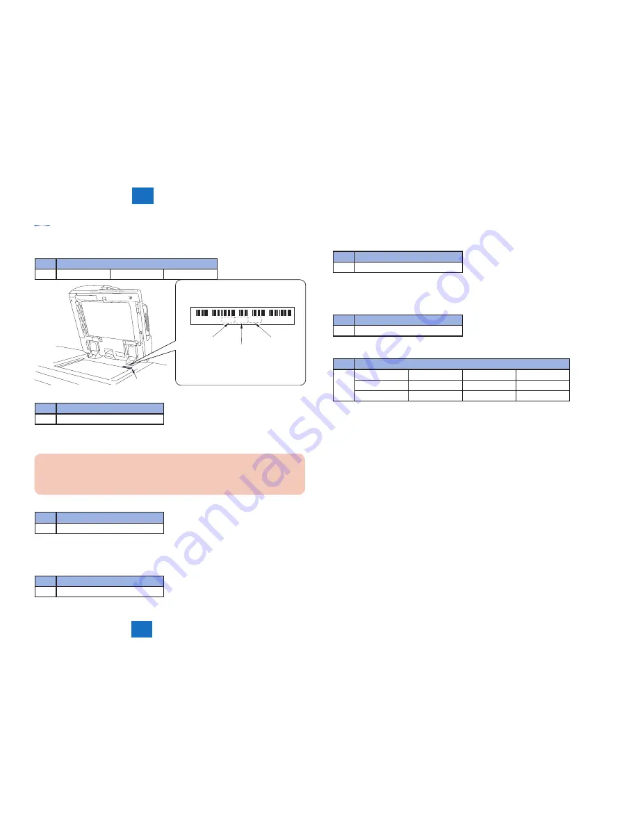
Processing after Copyboard Glass Replacement
1) Input the white level data (barcode value in the copyboard glass right upper) of the stand-
ard white plate.
Lv.
COPIER > ADJUST > CCD >
1
W-PLT-X
W-PLT-Y
W-PLT-Z
* 820686679349 *
W-PLT-X
W-PLT-Y
W-PLT-Z
Label
2) Perform sampling of the B&W shading target.
Lv.
COPIER > FUNCTION > CCD >
1
BW-TGT
3) Perform white level adjustment.
3-1) Set A4 or LTR paper in the copyboard glass, close the DADF.
CAUTION:
If white level is adjusted in the small width paper, there is possibility that it will not
adjust.
3-2) Perform service mode item.
Lv.
COPIER > FUNCTION > CCD >
1
DF-WLVL1
3-3) Remove the paper from copyboard glass, set it in the DADF document pickup tray.
3-4) Perform service mode item.
Lv.
COPIER > FUNCTION > CCD >
1
DF-WLVL2
3-5) Again, Set A4 or LTR paper in the copyboard glass, close the DADF.
3-6) Perform service mode item.
Lv.
COPIER > FUNCTION > CCD >
1
DF-WLVL3
3-7) Remove the paper from copyboard glass, set it in the DADF document pickup tray.
3-8) Perform service mode item.
Lv.
COPIER > FUNCTION > CCD >
1
DF-WLVL4
4) Write the value in the service label (inside the PCB cover).
Lv.
COPIER > ADJUST > CCD >
1
SH-TRGT
DFTAR-B
DFTBK-R
DFTBK-B
DFTAR-R
DFTAR-BW
DFTBK-G
DFTBK-BW
DFTAR-G
-
-
-
Summary of Contents for L1
Page 4: ...BLANK PAGE ...
Page 10: ...BLANK PAGE ...
Page 11: ...2 2 2 Technology Technology Technology Basic configuration Controls ...
Page 31: ...3 3 3 Periodic Service Periodic Service Periodic Servicing Periodic Servicing List ...
Page 41: ...5 5 5 Adjustmnet Adjustmnet Adjustments Overview Adjustment Method ...
Page 49: ...6 6 6 Installation Installation Installation Color Image Reader L1 ...
Page 78: ...Service Tools General Circuit Diagram Appendix Appendix Appendix ...


