background image

2

F-1-1

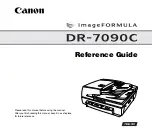
DC Controller PCB 2/8

 /  /  /  / iR1018 / iR1018J /  / iR1022A / iR1022F / iR1022i / iR1022iF / 

A

6

5

4

3

2

1

D

C

B

J

J

J1 P

J

J1 P

J

J1 P

J

J1 P

J

J1 P

J

J1 P

J

P

P

P

J14P

J14P

4P

J14P

4P

P

P

P

P

J14P

J

J

J7

J7P

J

P

P

J 3P

P

J 3P

J1 P

P

P

GND

VCC

GND

VCC

GND

VCC

4P

J1 P

E

RESET

BDO

NSMFG_I

NSMACC

NSMDEC

BDI_I

CNT2

CNT1

CNT0

P47/PWM1

P46

P27

P26/INT2

NDMFG_I

NDMACC

NDMDEC

TSI_I

TSO

TCK

P25

NMMFG I

NMMACC

NMMDEC

P24

P23

P22

P21

P20

TEST

RSTX

MOD2

MOD1

MOD0

X1

X0

VSS3

P45/USI

P44/USO

P43/USCK

P42

P41

P40

P37

P36/SI

P35/SO

P34/SCK

CT

RT

VCC1

VSS1

P33/INT1

P32

P31/PWM0

P30

P17

P16

P15

P14

P13

P67/AN7

P66/AN6

P65/AN5

P64/AN4

P63/AN3

P62/AN2

P61/AN1

P60/AN0

AVCC

AVR

AVSS

P12

P11/INT0

P10

P07

P06

P05

P04

NTNRCK

NFSRPWM

NFSRCK

NTRFMCK

NTRPWM

NTRFPCK

NDEVDCPWM

NDEVDCCK

DEVACCK

NPRDCCK

NPRDCPWM

NPRACCK

NPRIPWM

VSS2

P03

P02

P01

P00

SCLK

SCO

SCI I

VCC0

VSS0

HUMSNS

R190

12

R191

2

1

R170

2

1

C129

TNRCHKA

TNRCHKD

1

2

R171

TRCRNT

CRGSNS

+3.3R

2

1

R176

R174

12

C128

R187

+3 3R

+3.3R

2

1

C114

+3.3R

12

C115

100

99

98

97

96

95

94

93

92

91

90

89

88

87

86

85

84

83

82

81

80

79

78

77

76

75

74

73

72

71

70

69

68

67

66

65

64

63

62

61

60

59

58

57

56

55

54

53

52

51

50

49

48

47

46

45

44

43

42

41

40

39

38

37

36

35

34

33

32

31

30

29

28

27

26

25

24

23

22

21

20

19

18

17

16

15

14

13

12

11

10

9

8

7

6

5

4

3

2

1

IC101

2

4

1

IC102

S125

MM_BRAKE

ZEROX

+3.3R

+3.3R

2

1

R123

VDO2

VDO2

VDO1

VDO1

12

C102

2

1

C117

3

2

1

ETH101

OPCCHK

ESS

SC

SCLK

BDO

1

J104

RL_DR

PRACCK

DISPWM

DVDCON

PRACON

DISDCCK

2

3

1

41

1

IC105

RESET

2

1

C107

RLDRV

+24R

CCRT

MFP_SLEEP

NEX_RES_OUT

MM_FG

MM_ACC

MM_DEC

CLK

SO

SI

STRB

12

R167

ESS

NEX_RES_OUT

FLOCK

OP_P_SNS

OPCSTSL

FANON

CST_P_SNS

MP_P_SNS

RGSNS

P_FULL_SNS

1

J103

CSTSL

MPSL

DUPSL

RGCL

FWD

+3 3R

2

1

R168

+3.3R

1

2

JP102

2

1

JP101

12

C131

2

1

C130

2

1

R172

R117

12

R169

2

1

R104

+24U

2

1

R113

2

1

R166

2

1

C126

12

X101

2

1

C127

12

R125

+3.3R

1

2

C108

12

0.1U,25V

C113

+3.3R

MFP_SLEEP

12

C110

+3.3R

12

R114

+3.3R

BDO

R121

2

1

R102

BDI

2

1

C105

+3.3R

1

2

R165

2

1

D101

+3.3R

21

D102

2

1

C120

+3.3R

1

2

R122

SCLK

12

R107

12

R105

+5R

1

2

C118

21

C103

CNT0

5

3

S125

IC104

3

5

IC102

S125

+3.3R

12

R128

2

1

R127

2

1

R124

+3.3R

3

5

IC103

S125

2

1

C106

CCRT

+5R

2

1

C111

1

2

R115

2

1

C112

R120

2

1

C109

2

4

1

S125

IC104

2

1

R116

2

4

1

IC103

S125

2

1

R112

8

J102

2

1

R106

1

2

R101

1

J102

11

J102

12

J102

13

J102

10

J102

7

J102

4

J102

3

J102

2

J102

6

J102

5

J102

9

J102

CNT2

CNT1

2

1

R103

7

J101

1

J101

2

J101

3

J101

4

J101

5

J101

6

J101

1

2

R132

2

1

R126

1

2

R129

R131

R133

1

2

R118

2

1

R119

12

C101

2

1

R130

+3.3R

12

C116

1

2

C104

21

C119

SC

+5R

+24R

PRDCON

DVACCK

DCCK

DCPWM

TRPCK

TRPWM

TRNCK

SUBTH

MAINTH

TN_FULL

POSNS

SM_DEC

SM_ACC

2

J103

3

J103

4

J103

5

J103

6

J103

7

J103

8

J103

9

J103

10

J103

11

J103

12

J103

13

J103

14

J103

+24R

FSRDRV

2

J104

3

J104

4

J104

5

J104

6

J104

7

J104

8

J104

9

J104

10

J104

11

J104

12

J104

13

J104

14

J104

15

J104

16

J104

17

J104

2

1

C140

fineline6

Summary of Contents for iR1018

Page 1: ...Sep 22 2006 Service Manual iR1018 1019 1022 1023 Series fineline6 ...

Page 2: ...fineline6 ...

Page 3: ... arises In the event of major changes in the contents of this manual over a long or short period Canon will issue a new edition of this manual The following paragraph does not apply to any countries where such provisions are inconsistent with local law Trademarks The product names and company names used in this manual are the registered trademarks of the individual companies Copyright This manual ...

Page 4: ...ng care to avoid combustion fire Indicates an item prohibiting disassembly to avoid electric shocks or problems Indicates an item requiring disconnection of the power plug from the electric outlet Indicates an item intended to provide notes assisting the understanding of the topic in question Indicates an item of reference assisting the understanding of the topic in question Provides a description...

Page 5: ...o indicate Low The voltage value how ever differs from circuit to circuit In addition the asterisk as in DRMD indicates that the DRMD signal goes on when 0 In practically all cases the internal mechanisms of a microprocessor cannot be checked in the field Therefore the operations of the microprocessors used in the machines are not discussed they are explained in terms of from sensors to the input ...

Page 6: ...fineline6 ...

Page 7: ...he User 1 17 1 2 4 1 User Maintenance Items 1 17 1 2 4 2 Cleaning 1 17 1 2 5 Safety 1 19 1 2 5 1 Safety of Toner 1 19 1 2 5 2 Safety of the Laser Light 1 19 1 2 5 3 CDRH Regulations 1 19 1 2 5 4 Handling the Laser Unit 1 19 1 2 5 5 Point to Note about Fire 1 20 1 2 5 6 Cautions as to the replacement and disposal of lithium battery 1 20 1 2 6 Product Specifications 1 21 1 2 6 1 Product Specificatio...

Page 8: ...argement Reduction 4 3 4 3 1 1 Magnification Change in Vertical Scan Direction 4 3 4 3 1 2 Magnification Change in Horizontal Scan Direction 4 3 4 3 2 Dirt Sensor Control 4 4 4 3 2 1 Outline 4 4 4 4 Parts Replacement Procedure 4 6 4 4 1 Copyboard glass 4 6 4 4 1 1 Removing the Copyboard Glass 4 6 4 4 1 2 Procedure after Replacing the Copyboard Glass equipped with SEND functions 4 6 4 4 2 Reader Co...

Page 9: ...6 7 6 1 1 Removing the Cassette Pickup Roller 7 6 7 6 2 Cassette Paper Sensor 7 6 7 6 2 1 Removing the Cassette Paper Sensor 7 6 7 6 3 Cassette Pickup Solenoid 7 6 7 6 3 1 Removing the Cassette Pickup Solenoid 7 6 7 6 4 Manual Pickup Roller 7 7 7 6 4 1 Removing the Manual Pickup Roller 7 7 7 6 5 Manual Feed Tray paper sensor 7 7 7 6 5 1 Removing the Manual Tray Sensor 7 7 7 6 6 Manual Feed Pickup ...

Page 10: ... 1 9 3 Power Supply System 9 2 9 3 1 Power Supply 9 2 9 3 1 1 Outline 9 2 9 3 1 2 Rated Output of the Power Supply PCB 9 2 9 3 2 Protection Function 9 3 9 3 2 1 Protective Functions 9 3 9 4 Parts Replacement Procedure 9 4 9 4 1 External Covers 9 4 9 4 1 1 External Covers 9 4 9 4 2 Drive Unit 9 7 9 4 2 1 Removing the Main Drive Unit 9 7 9 4 2 2 Removing the Pickup Drive Unit 9 8 9 4 2 3 Removing th...

Page 11: ...ving the Drive Unit 10 9 10 4 4 Feed Frame Unit 10 9 10 4 4 1 Removing the Feed Frame Unit 10 9 10 4 5 ADF Motor Unit 10 10 10 4 5 1 Removing the ADF Motor 10 10 10 4 6 Pick up Feed Roller Unit 10 10 10 4 6 1 Removing the Pickup Feed Roller Unit 10 10 10 4 7 Pickup Roller 10 11 10 4 7 1 Removing the Pickup Roller 10 11 10 4 8 Original Separation Pad 10 11 10 4 8 1 Removing the Separation Pad 10 11...

Page 12: ...hanical System 12 3 12 4 2 1 Adjusting the Perpendicularity 12 3 12 4 3 Adjusting the Ellectrical System 12 3 12 4 3 1 Adjusting the Magnification 12 3 12 4 3 2 Adjusting the Horizontal Registration 12 3 12 4 3 3 Leading edge registration adjustment 12 4 Chapter 13 Correcting Faulty Images 13 1 Making lnitial Checks 13 1 13 1 1 Site Environment 13 1 13 1 2 Checking the Paper 13 1 13 1 3 Checking t...

Page 13: ...ions of Bit 7 15 9 15 3 5 SSSW SW05 15 9 15 3 5 1 List of Functions 15 9 15 3 5 2 Detailed Discussions of Bit 1 15 9 15 3 5 3 Detailed Discussions of Bit 2 15 10 15 3 6 SSSW SW12 15 10 15 3 6 1 List of Functions 15 10 15 3 7 SSSW SW13 15 10 15 3 7 1 List of Functions 15 10 15 3 7 2 Detailed Discussions of Bit 2 15 10 15 3 8 SSSW SW14 15 11 15 3 8 1 List of Functions 15 11 15 3 8 2 Detailed Discuss...

Page 14: ...nning 15 19 15 6 3 026 Distance from the standby position of CIS to the shading start point 15 19 15 6 4 031 Vertical scan start position adjustment 15 19 15 6 5 032 Horizontal scan start position adjustment 15 19 15 6 6 033 Vertical scan magnification correction 15 19 15 6 7 034 Horizontal scan magnification correction 15 19 15 6 8 035 036 Reader motor speed change 15 19 15 6 9 041 Vertical scan ...

Page 15: ...of the copy 15 24 15 8 Registration of Accessories ACC 15 25 15 8 1 Accessory Registration 15 25 15 9 Display of Counter Information COUNTER 15 25 15 9 1 Counters 15 25 15 9 2 Clearing Counters 15 25 15 10 Service Report REPORT 15 27 15 10 1 Report Output 15 27 15 10 2 System Data List 15 27 15 10 3 System Dump List 15 27 15 10 4 Counter List 15 29 15 10 5 Error Log List 15 29 15 10 6 Spec List 15...

Page 16: ...ownloading BOOT 16 4 16 3 2 1 Downloading Procedure 16 4 16 3 3 Other Upgrade Methods 16 9 16 3 3 1 Downloading the PCL Software 16 9 Chapter 17 Service Tools 17 1 Service Tools 17 1 17 1 1 Special Tools 17 1 fineline6 ...

Page 17: ...Sep 22 2006 Circuit Diagram iR1018 1019 1022 1023 Series fineline6 ...

Page 18: ...23 VDO2 VDO2 VDO1 VDO1 1 2 C102 2 1 C117 3 2 1 ETH101 OPCCHK ESS SC SCLK BDO 1 J104 RL_DR PRACCK DISPWM DVDCON PRACON DISDCCK 2 3 1 4 11 IC105 RESET 2 1 C107 RLDRV 24R CCRT MFP_SLEEP NEX_RES_OUT MM_FG MM_ACC MM_DEC CLK SO SI STRB 1 2 R167 ESS NEX_RES_OUT FLOCK OP_P_SNS OPCSTSL FANON CST_P_SNS MP_P_SNS RGSNS P_FULL_SNS 1 J103 CSTSL MPSL DUPSL RGCL FWD 3 3R 2 1 R168 3 3R 1 2 JP102 2 1 JP101 1 2 C131...

Page 19: ...Sep 22 2006 General Timing Chart General Circuit Diagram iR1018 1019 1022 1023 Series fineline6 ...

Page 20: ...Contents 1 General Timing Chart 1 ADF 1 Reader Unit 2 Printer 3 2 General Circuit Diagram 5 General Circuit Diagram 5 fineline6 ...

Page 21: ...Oct 2 2006 PARTS CATALOG iR1018 1018J 1019J 1022 1022A 1022F 1022i 1022iF 1022J 1023 1023iF 1023N fineline6 ...

Page 22: ...30 CONTROL PANEL ASSEMBLY 2 18 160 COPYBOARD COVER ASSEMBLY 2 20 161 ADF ASSEMBLY 2 22 162 DOCUMENT TRAY ASSEMBLY 2 25 163 OPEN CLOSE PANEL ASSEMBLY 2 27 164 PAPER FEED ASSEMBLY 2 30 250 MAIN DRIVE ASSEMBLY 2 33 251 REVERSE DRIVE ASSEMBLY 2 35 300 CASSETTE 2 37 301 CASSETTE CHINA 2 39 310 PAPER PICK UP ASSEMBLY 2 41 315 MULTI PAPER PICK UP TRAY ASS Y 2 43 320 REGISTRATION ASSEMBLY 2 46 400 READER ...

Page 23: ...Sep 22 2006 Portable Manual iR1018 1019 1022 1023 Series fineline6 ...

Page 24: ...ass if equipped with SEND functions 4 2 3 Electrical Components 4 2 3 1Procedure after Replacing the Image Processor PCB 4 2 3 2Actions to Take before All Clearing Backing up the User Data 4 Chapter 3 Error Code 3 1 Error Code Details 7 3 1 1Error Code Details 7 3 2 Jam Code 8 3 2 1Jam Codes Main body 8 3 2 2Jam Codes ADF 8 Chapter 4 User Mode Items 4 1 User Mode Items 11 4 1 1COMMON SETTINGS 11 4...

Page 25: ...5 hooking detection time 26 5 1 3 9 016 time length to first response at time of fax tel switchover 26 5 1 3 10 017 pseudo RBT signal pattern ON time length 018 pseudo RBT signal pattern OFF time length short 019 pseudo RBT signal pattern OFF time length long 26 5 1 3 11 020 pseudo CI signal pattern ON time length 021 pseudo CI signal pattern OFF time length short 022 pseudo CI signal pattern OFF ...

Page 26: ... correction value X of standard white plate equipped with SEND functions 32 5 1 4 22 214 XYZ correction value Y of standard white plate equipped with SEND functions 32 5 1 4 23 215 XYZ correction value Z of standard white plate equipped with SEND functions 32 5 1 5 Printer Function Settings PRINTER 32 5 1 5 1 Service Soft Switch Settings 32 5 1 5 2 Numeric Parameter Settings NUMERIC Param 34 5 1 6...

Page 27: ...CB 62 7 1 7Relay PCB 62 7 1 8Control Panel PCB 62 7 1 9NCU PCB if equipped with fax functions 62 7 1 10Network PCB if equipped with network functions 62 7 1 11Modular Jack PCB if equipped with fax functions 62 7 1 12Modem PCB if equipped with fax functions 62 7 2 System Construction 64 7 2 1System Configuration 64 7 3 Product Specifications 67 7 3 1Product Specifications 67 7 3 2ADF Specifications...

Page 28: ...Sep 22 2006 Installation Procedure iR1018 1019 1022 1023 Series fineline6 ...

Page 29: ...tents Contents Chapter 1 Installation Procedure 1 1 Installing the Card Reader 2 1 1 1Points to Note 2 1 1 2Checking the Contents 2 1 1 3Installation Procedure 4 1 1 4Registering the Card IDs 10 fineline6 ...

Reviews: