Canon imagePROGRAF iPF815 Service Manual Download Page 319

5

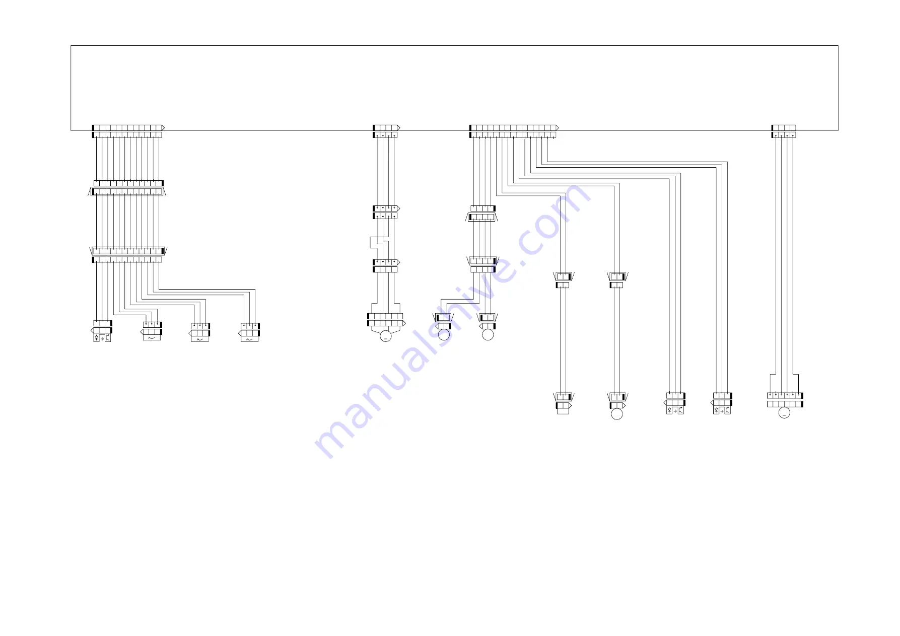
General Circuit Diagram (5/7)

F-1-5

2

1

2

3

4

5

6

1

2

3

4

5

6

M

1

2

1

CL

2

1

CL

C2

C3

M3

RGV8(SNS3V)

GND

1

2

3

P

1

1

1

2

3

4

5

6

7

8

9

10

11

12

RGV19(VM_26V_2)

RGV19(VM_26V_2)

RGV19(VM_26V_2)

RGV7(SNS5V2)

2

1

CL

M

2

3

S

2

1

SL

1

2

3

2

3

P

S

2

3

P

S

1

2

3

SR3

SP1

SR4

M2

PICKUP_ATUKAIJO__SNS_1*

KYUUSHI_SNS_F*

YOUSHIHABA_SNS*

GND

OUT_LFNIP_B

OUT_LFNIP_AB

UT_LFNIP_A

J3902

RGV7(SNS5V2)

GND

OUT_LFNIP_BB

PICKUP_CL_OUT

KYUUSHI_CL_OUT

FLAPPER_SOL_OUT

PINCH_CL_OUT

RGV8(SNS3V)

GND

S1

SR2

RGV8(SNS3V)

RGV19(VM_26V_2)

1

GND

KYUUSHI_SNS_R1*

RGV7(SNS5V2)

GND

J3801

J3901

PINCH_OPEN_SNS*

PINCH_CLOSE_SNS*

J4003

C1

SP14

SP13

OUT_ZENMENM_B

OUT_ZENMENM_A

OUT_ZENMENM_AB

OUT_ZENMENM_BB

2

1

J3916H

J3915DH

1

2

3

J3919

1

2

3

J3917

1

2

J3916

12 11 10 9

8

2

3

4

5

6

1

7

J3816D

12

11

10

9

8

2

3

4

5

6

1

7

J3811L

1

2

3

4

J3910L

1

2

3

4

1

2

3

4

J3911D

J3911DH

2

3

4

1

J4031L

2

3

4

1

2

3

4

1

J4032D

2

3

4

1

J4031D

J3910LH

1

2

3

4

J3910D

J3816DH

J3811LH

J3914H

1

2

J3914

15

14

13

12

11

10

9

8

2

3

4

5

6

1

7

15

14

13

12

11

10

9

8

2

3

4

5

6

1

7

12 11 10 9

8

2

3

4

5

6

1

7

J3811D

2

3

4

1

2

3

4

1

12

11

10

9

8

2

3

4

5

6

1

7

2

3

1

J3815

2

3

1

J3814

2

3

1

J3813

3

4

5

6

1

2

3

4

5

6

1

2

J3921

1

2

J3918L

J3918DH

1

2

J3918D

1

2

J3915L

1

2

J3915D

1

2

3

J3812

2

3

4

1

2

3

4

1

12

11

10

9

8

2

3

4

5

6

1

7

J3816L

Main controller PCB (5/7)

Roll media 
pick-up 
cam sensor

Roll media 
pick-up motor

Roll media 
pick-up cam 
clutch

Roll media 
pick-up
roller 
clutch

Flapper 
solenoid

Pinch roller 
pressure 
clutch

Pinch roller 
releace 
detection 
sensor

Pinch roller 
pressure
detection
sensor

Pinch roller 
pressure
motor

Roll media 
detection 
sensor

Roll media
pick-up roller 
paper 
detection 
sensor

Roll media 
width detection 
sensor

Summary of Contents for imagePROGRAF iPF815

Page 1: ...SERVICE MANUAL imagePROGRAF iPF815 COPYRIGHT 2017 CANON INC CANON imagePROGRAF iPF815 Rev 1 PRINTED IN U S A February 27 2017 Rev 1...

Page 2: ......

Page 3: ...need arises In the event of major changes in the contents of this manual over a long or short period Canon will issue a new edition of this manual The following paragraph does not apply to any countri...

Page 4: ...uiring care to avoid combustion fire Indicates an item prohibiting disassembly to avoid electric shocks or problems Indicates an item requiring disconnection of the power plug from the electric outlet...

Page 5: ...ed to indicate Low The voltage value how ever differs from circuit to circuit In addition the asterisk as in DRMD indicates that the DRMD signal goes on when 0 In practically all cases the internal me...

Page 6: ......

Page 7: ...1 5 5 Ink Tank Cover Inside 1 20 1 6 Basic Operation 1 21 1 6 1 Operation Panel 1 21 1 6 2 Main Menu 1 22 1 6 3 Basket Unit 1 44 1 7 Safety and Precautions 1 50 1 7 1 Safety Precautions 1 50 1 7 1 1...

Page 8: ...33 2 3 3 3 Cutter Unit 2 36 2 4 Printer Electrical System 2 37 2 4 1 Outline 2 37 2 4 1 1 Overview 2 37 2 4 2 Main Controller 2 39 2 4 2 1 Main controller PCB components 2 39 2 4 3 Carriage Relay PCB...

Page 9: ...and closing ink supply valves 4 51 4 3 19 Draining the ink 4 52 4 4 Applying the Grease 4 53 4 4 1 Applying the Grease 4 53 4 5 Adjustment and Setup Items 4 56 4 5 1 Adjustment Item List 4 56 4 5 2 Pr...

Page 10: ...on 7 1 7 1 2 Map of the Service Mode 7 2 7 1 3 Details of Service Mode 7 8 7 1 4 Sample Printout 7 16 7 2 Special Mode 7 20 7 2 1 Special Modes for Servicing 7 20 Chapter 8 ERROR CODE 8 1 Outline 8 1...

Page 11: ...Chapter 1 PRODUCT DESCRIPTION...

Page 12: ......

Page 13: ...5 3 Top Cover Inside 1 19 1 5 4 Carriage 1 20 1 5 5 Ink Tank Cover Inside 1 20 1 6 Basic Operation 1 21 1 6 1 Operation Panel 1 21 1 6 2 Main Menu 1 22 1 6 3 Basket Unit 1 44 1 7 Safety and Precaution...

Page 14: ......

Page 15: ...mounted type printer and is capable of output to either roll media or cut sheet F 1 1 T 1 1 1 Upper Cover 9 Ink Tank Cover 2 Ejection Guide 10 Operation Panel 3 Roll Holder Slot 11 Release Lever 4 Ro...

Page 16: ...Chapter 1 1 2 F 1 2 T 1 2 1 Ethernet Connector 5 Power Supply Connector 2 USB Port 6 Carrying Handles 3 Manual Pocket 7 Accessory Handles 4 Madia Take up Unit Connector 2 1 3 4 5 7 6 6...

Page 17: ...s installed for better print job management and for driving on night time Ready for CAD drawings output on the HP GL 2 and HP RTL The product can be fitted with a wheeled output stacker as an option t...

Page 18: ...s paper tubes having inside diameters of both 2 and 3 inches It is furnished with attachments for 2 and 3 inch diameter paper tubes The roll holder clamps the paper tube of a roll not exceeding 150 mm...

Page 19: ...ith casters so that the printer can be easily moved F 1 10 1 2 7 Wheeled Output Stacker 0020 5422 This is a output stacker on wheels that is attached to the front of the printer F 1 11 T 1 3 1 Basket...

Page 20: ...le the motor automatically when an overload occurs while spooling a roll Additional features of the media take up unit include An adapter may be installed to support a 3 inch paper tube Roll media can...

Page 21: ...as paper out while printing a print job it can resume the print operation as soon as the errors are cleared without retransmission from the host computer Higher print work efficiency Print jobs can b...

Page 22: ...and right margins The printable area may vary with each type of paper media used Printable area Cut sheet Internal area excluding a 3 mm top margin a 23 mm bottom margin and 3 mm left and right margin...

Page 23: ...ase lever position detection Yes Remaining roll media detection Yes Feed roller rotation detection Yes Cutter positin detection Yes Operating noise Operating Approx 52dB A or less Standby Approx 35dB...

Page 24: ...Bi directional 1200x1200 MBK High 8 Bi directional 2400x1200 MBK Economy Bond Paper Office Document Standard 4 Bi directional 1200x1200 MBK Line Document Text Draft 2 Bi directional 1200x1200 MBK Stan...

Page 25: ...onal 1200x1200 MBK High 8 Bi directional 2400x1200 MBK Highest 12 Bi directional 2400x1200 MBK High Resolution Barrier Paper 180g Image Standard 4 Bi directional 1200x1200 MBK High 8 Bi directional 24...

Page 26: ...directional 2400x1200 PBK Highest 16 Bi directional 2400x1200 PBK Instant Dry Papers Glossy 200g Image Standard 6 Bi directional 1200x1200 PBK High 8 Bi directional 2400x1200 PBK Highest 16 Bi directi...

Page 27: ...tandard 6 Bi directional 1200x1200 MBK High 8 Bi directional 2400x1200 MBK Highest 16 Bi directional 2400x1200 MBK Water Resistant Paper Art Canvas Image Standard 6 Bi directional 1200x1200 MBK High 8...

Page 28: ...16 Bi directional 2400x1200 MBK Adhesive Synthetic Paper Image Standard 6 Bi directional 1200x1200 MBK High 8 Bi directional 2400x1200 MBK Highest 16 Bi directional 2400x1200 MBK Outdoor Polypropylen...

Page 29: ...ional 2400x1200 PBK Highest 16 Bi directional 2400x1200 PBK SPECIAL 6 Image Standard 6 Bi directional 1200x1200 MBK High 8 Bi directional 2400x1200 MBK Highest 16 Bi directional 2400x1200 MBK SPECIAL...

Page 30: ...pair 5 Interface connector Printer side Series B receptacle compliant with USB standard Cable side Series B plug compliant with USB standard b Network standard 1 Interface type Interface compliant wi...

Page 31: ...Ink tank cover Open this cover to replace ink tanks 10 Operation panel Operate the printer or view its status from this panel 11 Release lever Releases the paper retainer Pull up this lever to front...

Page 32: ...3 Manual pocket Have the printer manual stowed in this pocket 4 Media take up unit connector Insert the cable a media take up unit option into this connector 5 Power Supply Connector Connect the power...

Page 33: ...avel 7 Borderless printing ink reservoir Receives inks overflowing the outside of the paper during borderless printing 8 Cleaner brush Sweeps off paper dust from the platen surface when cleaning the i...

Page 34: ...ver up and down to replace the ink tank To open raise the stopper of the lever until it won t go farther and then push it to the front To close depress the stopper until it clicks 3 Ink lamp red Indic...

Page 35: ...er is in offline mode to manually feed roll media Press this button when the printer is in menu mode to view the next item or setting 12 button Press this button when the printer is in menu mode to vi...

Page 36: ...e and a menu related to parameters such as a message language 1 Main menu operations a How to enter the Main menu To enter the Main menu press the Menu button on the operation panel b How to exit the...

Page 37: ...Reel 10 Disable Enable Media Menu Cut Sheet Type Plain Paper 5 Plain Paper HQ 5 Plain Paper HG 5 Recycled Coated 5 Coated Paper 5 HW Coated 5 Ex HW Coated 5 Premium MatteP 5 Glossy Photo 5 Semi Gl Ph...

Page 38: ...Paper 5 CAD Matte Film 5 CAD Clear Film 5 Special Here the number is 1 to 10 5 Roll Media Type Plain Paper 5 Plain Paper HQ 5 Plain Paper HG 5 Recycled Coated 5 Coated Paper 5 HW Coated 5 Ex HW Coated...

Page 39: ...er 5 CAD Matte Film 5 CAD Clear Film 5 Special Here the number is 1 to 10 5 Roll Length Set 1 2 m 16 feet 16 ManageRemainRoll Off On Paper Details The paper type is displayed here 5 Roll DryingTime Of...

Page 40: ...atic Fixed CutDustReduct Off On NearEnd Sht Mrgn 3mm 20mm Return Defaults No Yes Job Management Print Job Job List Choose a print job Delete Preempt Jobs Stored Job Mailbox List Enter a password if on...

Page 41: ...olor CAD 1 Color CAD 2 Color CAD 3 Color CAD 4 Color CAD 5 Color CAD 6 Print Quality Fast Standard High Input Resolution 600dpi 300dpi Print Economy Off On Paper Manager Paper Source Automatic Roll Pa...

Page 42: ...th value Color 0 255 Line Attributes No Setting Circle Setting Palette B Choose a pen number Indicates Width Color and Line Attributes Specify the values of Width Color and Line Attributes Factory Cho...

Page 43: ...j No Yes Auto Print Off On Manual Head Adj 12 No Yes Auto Band Adj Standard Adj No Yes Advanced Adj No Yes Manual Band Adj No Yes Adjust Length 3 A High No Yes B Standard Draft No Yes Head Inc Adj No...

Page 44: ...fault G W 0 0 0 0 to 255 255 255 255 NetWare 18 NetWare On Off Frame Type 6 Auto Detect Ethernet 2 Ethernet 802 2 Ethernet 802 3 Ethernet SNAP Print Service 6 BinderyPServer RPrinter NDSPServer NPrint...

Page 45: ...vel 3 System Setup Warning Buzzer Off On Detect Mismatch Pause Warning None Skip Take Up Err 10 Off On Keep Media Size Off On Paper Size Basis Sht Selection 1 ISO A3 13 x19 Super B Sht Selection 2 ISO...

Page 46: ...ens Cairo 3 Moscow 4 Eerevan Baku 5 Islamabad 6 Dacca 7 Bangkok 8 Hong Kong 9 Tokyo Seoul 10 Canberra 11 NewCaledonia 12 Wellington 12 Eniwetok 11 Midway is 10 Hawaii AHST 9 Alaska AKST 8 Oregon PST 7...

Page 47: ...Auto Feed for the loaded roll 14 Not displayed if IP Mode is Automatic 16 Follows the setting in Length Unit 17 Leading edge is not available as a setting option in the Paper Detailed Settings dialog...

Page 48: ...vel Menu Durng Prtng Head Cleaning Head Cleaning A Head Cleaning B Fine Band Adj 5 to 5 Information System Info Error Log 1 xxxxxxxx xxxx 2 xxxxxxxx xxxx Job Log Choose from information about the late...

Page 49: ...2 Adjust Printer Adjust the Printhead alignment or amount of feed by printing a test pattern Interface Setup Configure the EOP timer and network settings Maintenance Access maintenance settings when r...

Page 50: ...r printing quality at the leading edge Note that if you choose 5mm it may lower the printing quality at the leading edge and affect feeding accuracy The printed surface may be scratched and ink may ad...

Page 51: ...n the most recently printed job User Name Displays the name of the user who has transmitted the job Page Count Displays the number of sheets of the job Job Status Displays the result of processing of...

Page 52: ...ct On to print pages when they are tiled fully to the roll width instead of printing them one by one Nesting WaitTime Set the time to elapse before printing Cut Lines Select On to print perforated lin...

Page 53: ...d Adj Standard Adj Choose Yes to have the printer print and read a band adjustment test pattern for automatic adjustment of the feed amount Advanced Adj Choose this option when using paper other than...

Page 54: ...oose Register Setting Ethernet Driver Auto Detect Specify the communication method To apply your changes choose Register Setting Choose On for automatic configuration of the LAN communication protocol...

Page 55: ...per printed page Choose 10 pages to check once per ten printed pages Choose Automatic to have the printer automatically adjust the timing for checks based on the frequency of nozzle use CarriageScanW...

Page 56: ...etween 0 and 9999999 Viewing and configuration by administrators only IPv4 Settings Change Password Init Admin Pswd Viewing and configuration by administrators and only viewing by other users Interfac...

Page 57: ...e version of the printer and firmware Boot Displays the version of the boot ROM MIT Displays the version of the MIT database format s n Displays the printer s serial number MAC Displays the MAC addres...

Page 58: ...sheet When printing multiple pages remove each sheet after it is printed Before using the Output Stacker remove the Rewind Spool If you do not it may prevent printed documents from being held correct...

Page 59: ...ntly to release the lock lower the stacker toward the front and push it all the way back F 1 25 2 Remove the front Basket Rod from the left and right Basket Rods and remove the back Basket Rod and the...

Page 60: ...Adapter leaving the Rod Holder attached and put it in front of the printer F 1 27 4 Pull out the Basket Hooks from the left and right side of the Ejection Guide F 1 28 5 Attach the Basket Rod to the B...

Page 61: ...to the Rod Holder F 1 30 b Stowing the Output Stacker Stow the Output Stacker if you will use the Media Take up Unit or if you will not use the Output Stacker for an extended period 1 Lift the front...

Page 62: ...asket Rod from the left and right Basket Rods Roll up the Basket Cloth and put it at the back of the Bottom Stand Stay F 1 32 F 1 33 Arrange the Basket Cloth and Basket Rod so they do not interfere wi...

Page 63: ...Chapter 1 1 49 3 Push in the left and right Basket Rods toward the back all the way until they stop F 1 35...

Page 64: ...it To prevent accidents the upper cover of the printer is locked during printing so that it does not open If the upper cover is opened in the online offline mode the carriage motor feed motor and othe...

Page 65: ...ch unit F 1 37 Although the ink is not harmful to the human body it contains organic solvents Avoid getting the ink in your mouth or eyes Flush well with water and see a doctor if contact occurs In ca...

Page 66: ...cted in the printer by the airflow However uncollected ink mist may stain the platen unit carriage unit carriage shaft unit external unit or purge unit These stains may soil the print media or hands a...

Page 67: ...the printer with the cover removed be extremely careful to avoid electric shock and shorting contacts F 1 39 1 Operation panel 8 Power supply PCB 2 Carriage relay PCB 9 Main controller PCB 3 Head rela...

Page 68: ...ng standby due to an error in order to protect the printhead and avoid ink leakage If the power cord is accidentally unplugged turn off the Power button reconnect the power cord and then turn on the P...

Page 69: ...atter from entering the ink port install the unpacked ink tank in the printer immediately F 1 41 2 Handling the Ink Tank To prevent foreign matter from entering the ink flow path and causing ink sucti...

Page 70: ...eir electrical characteristics In particular never touch the printhead contact 1 F 1 43 2 Fixing the Carriage After completion of printing the carriage is mechanically locked by the lock arm in the pu...

Page 71: ...until the error is cancelled Be careful that the waste ink does not splash when you remove the used maintenance cartridge from the printer MEMO This printer has an EEPROM in the maintenance cartridge...

Page 72: ...ber of cleanings 4 On replacement of supplies After supplies have been replaced execute INITIALIZE PARTS COUNTER PARTS xx in service mode to initialize clear the parts counter information For the cons...

Page 73: ...with a lithium battery to back up various data Risk of explosion if battery is replaced by an incorrect type Dispose of used batteries according to the instructions For CA USA Only Included battery co...

Page 74: ......

Page 75: ...Chapter 2 TECHNICAL REFERENCE...

Page 76: ......

Page 77: ...nit 2 22 2 3 2 3 1 Functions of Carriage Unit 2 22 2 3 2 3 2 Structure of Carriage Unit 2 23 2 3 2 4 Printhead 2 25 2 3 2 4 1 Structure of Printhead 2 25 2 3 2 5 Purge Unit 2 26 2 3 2 5 1 Functions of...

Page 78: ...elay PCB components 2 42 2 4 7 Power Supply 2 42 2 4 7 1 Power supply block diagram 2 42 2 5 Detection Functions with Sensors 2 43 2 5 1 Covers 2 43 2 5 2 Ink passage system 2 44 2 5 3 Carriage system...

Page 79: ...tor Lift motor Purge motor Valve motor Cutter motor Roll media pick up motor Pinch roller pressure motor HP maintenance jet pump motor Carriage HP sensor Pump encoder sensor Pump cam sensor Media sens...

Page 80: ...on the printheads and the printer temperature from the latch IC on the carriage board and transmit them to the ASIC IC1 The ASIC IC1 also receives mask pattern data from the firmware installed in flas...

Page 81: ...ed split in 40 20 or 10 nozzle blocks according to the Block Enable information in the even numbered nozzle data and odd num bered nozzle data Each selected block of nozzles is impressed with a Heat E...

Page 82: ...g signal internal signal which is generated by dividing the ENCODER_A signal detected at the 150 dpi timing into 16 equal sections Printing in the forward direction is triggered at the leading edge of...

Page 83: ...feed system initialization Recovery system initialization Carriage position initialization Remaining ink level detection Waste ink level detection Power on automatic recovery operation Capping Waiting...

Page 84: ...ion and shuts down immediately Since printhead capping may or may not have been carried out properly reconnect the power cord to the wall out and turn on the power switch Making sure that the printer...

Page 85: ...eding Even in the same mode the printer operates in a different way depending on the media setting made using the printer driver a Draft mode In the draft mode image data is thinned out and a single b...

Page 86: ...Chapter 2 2 8 Printing Modes...

Page 87: ...Chapter 2 2 9...

Page 88: ...Bi directional 2400x1200 MBK Economy Bond Paper Office Document Standard 4 Bi directional 1200x1200 MBK Line Document Text Draft 2 Bi directional 1200x1200 MBK Standard 4 Bi directional 1200x1200 MBK...

Page 89: ...onal 1200x1200 MBK High 8 Bi directional 2400x1200 MBK Highest 12 Bi directional 2400x1200 MBK High Resolution Barrier Paper 180g Image Standard 4 Bi directional 1200x1200 MBK High 8 Bi directional 24...

Page 90: ...directional 2400x1200 PBK Highest 16 Bi directional 2400x1200 PBK Instant Dry Papers Glossy 200g Image Standard 6 Bi directional 1200x1200 PBK High 8 Bi directional 2400x1200 PBK Highest 16 Bi directi...

Page 91: ...tandard 6 Bi directional 1200x1200 MBK High 8 Bi directional 2400x1200 MBK Highest 16 Bi directional 2400x1200 MBK Water Resistant Paper Art Canvas Image Standard 6 Bi directional 1200x1200 MBK High 8...

Page 92: ...16 Bi directional 2400x1200 MBK Adhesive Synthetic Paper Image Standard 6 Bi directional 1200x1200 MBK High 8 Bi directional 2400x1200 MBK Highest 16 Bi directional 2400x1200 MBK Outdoor Polypropylen...

Page 93: ...ional 2400x1200 PBK Highest 16 Bi directional 2400x1200 PBK SPECIAL 6 Image Standard 6 Bi directional 1200x1200 MBK High 8 Bi directional 2400x1200 MBK Highest 16 Bi directional 2400x1200 MBK SPECIAL...

Page 94: ...ature Protection level 1 If the head temperature sensor DI sensor detects a temperature higher than the protection temperature it halts the carriage temporarily at the scan end position in the directi...

Page 95: ...e host computer to it 3 Job preservation Print jobs are in the common box a place of temporary data storage and in the personal box a place of permanent data storage Normal print jobs are stored in th...

Page 96: ...he carriage unit 2 the purge unit 3 and the maintenance cartridge 4 Its functions are to supply circulate and suck inks and more The paper path comprises the feed assembly 5 the upper roll media pick...

Page 97: ...e cartridge c Supplying inks while printing The ink supply valves are kept open while printing so that ink is constantly supplied to the printhead according to the negative pressure of the nozzle asse...

Page 98: ...by a rubber plug linking the ink passage of the ink to the printer c Air passage Depressing the ink tank fixer lever on the printer would cause an open hollow needle to pierce the air passage sealed b...

Page 99: ...the ink supply valve prevents ink leaks that may occur when the ink tube on the ink tank is released during replacement of the ink tank The ink supply valve is opened and closed by a valve open close...

Page 100: ...iage height increases or to result in head rubbing as the carriage height decreases To maintain an acceptable carriage height the lift motor is driven according to the selected paper type feeding meth...

Page 101: ...ht side of the carriage and the photointerrupter based carriage HP sensor on the right side of the printer When the linear scale position is set as a reference home position for use in subsequent posi...

Page 102: ...Service mode SERVICE MODE ADJUST GAP CALIB h Shaft cleaner The shaft cleaner located in the right side of the carriage helps keep the carriage shaft clean i Internal unit temperature sensor One therm...

Page 103: ...intervals in a zigzag pattern offering a total of 2 560 nozzles 1 200 dpi intervals F 2 13 b Nozzle assembly structure Inks supplied from the ink tanks are filtered through a mesh ink filter before be...

Page 104: ...e table below Cleaning mode Name of Service mode or PRINT INF Name of Main Menu Operation Description of cleaning Cleaning 1 CLN A 1 CLN M 1 Head Cleaning A Normal cleaning Removes dried ink from nozz...

Page 105: ...Normal strong Cleaning 5g Print operation aborted uncapped and no CR error occurring Cleaning 11 ink filling after head replacement 10g No heads are available Cleaning 10 ink filling on secondary tra...

Page 106: ...cularly to the head wipes the entire face of the printhead followed by a narrower blade wiping the nozzle assembly The wiper blades are cleaned before they are replaced at the wiping position after wi...

Page 107: ...sensor F 2 17 Purge motor HP maintenance jet pump motor HP maintenance jet suction pump HP maintenance jet pump encoder sensor HP maintenance jet tray Pump encoder sensor Suction pump Pump cam sensor...

Page 108: ...rning message is displayed When the quantity of the waste ink reaches 100 of the cartridge capacity a replacement prompt error message is displayed telling that the maintenance cartridge is full When...

Page 109: ...the printer produces the airflow that carries the ink mist to the mist fan unit F 2 19 A duct is located under the platen along with a platen ink BOX unit used for collecting waste ink during borderle...

Page 110: ...at drives the roll holder and sensors that detect the transport status of paper to feed paper in three different ways and transport and eject the paper lower roll unit is iPF851 850 841 840 825 820 on...

Page 111: ...media from the platen to the standby position before the transport of a roller from the other roll media pick up specified starts c Rewinding rolls While a roll media has been carried to the platen i...

Page 112: ...ll media Route of cut sheet Pinch roller pressure release shaft Pinch roller release detection sensor Pinch roller pressure detection sensor Pinch roller pressure motor Pinch roller pressure clutch Pi...

Page 113: ...Chapter 2 2 35 Paper feeds horizontally under the printheads on the carriage as it is kept level on the platen to prevent cockling F 2 23 Pinch roller Feed roller Feed motor...

Page 114: ...jection Whether cutting takes place or not depends on the relevant printer driver setting in the main menu The cutter in the cutter unit stands by at the cutter home position except when a roll media...

Page 115: ...he carriage relay PCB the head relay PCB and printhead which are mounted in the carriage the operation panel on the right upper cover and other electrical components such as sensors and motors The mai...

Page 116: ...Image data control function Heat pulse control function Interface control function Hard disk drive control function DI sensor reading control function Temperature reading control function Thermistor...

Page 117: ...ds the linear scale when the carriage moves thus generating the ink discharge timing It also counts the linear scale timing cycle using the reference clock to measure the carriage moving speed Dot cou...

Page 118: ...1 This IC generates a roll media pick up motor control signal based on the control signal from the ASIC i Driver IC IC4602 This IC generates a cutter motor control signal based on the control signal f...

Page 119: ...in the printhead and the head rank value for each color and outputs them to the main controller based on the control commands from the main controller Environment temperature read control function Out...

Page 120: ...Supply 2 4 7 1 Power supply block diagram 0012 6414 F 2 32 The power supply converts AC voltages ranging from 100V to 240V from the AC inlet to DC voltages for driving the ICs motor and others The vol...

Page 121: ...Pinch roller pressure release switch The microswitch based pinch rollerpressure release switch detects the status of the paper release lever When the paper release lever closes the switch is pressed...

Page 122: ...by the combination of the pump cam sensor detection and the control of pump motor rotation by the pump encoder sensor F 2 35 Valve open closed detection sensor Agitation cam sensor HP maintenance jet...

Page 123: ...harging nozzle detection is carried out at the following timings After the execution of Cleaning 1 Cleaning 2 Cleaning 3 Cleaning 6 or Cleaning 10 After the number of copies that has been set by the u...

Page 124: ...ts movement Lift cam sensor A photointerrupter based sensor After the sensor light is shielded by the flag the lift motor is driven by a predetermined number of pulses to regulate the separation betwe...

Page 125: ...is composed of four LEDs red blue green and infrared and two light sensitive sensors It detects the leading edge skewing and width of media and is used for adjustment of the registration head height a...

Page 126: ...detection sensor and the lower roll media width detection sensor detect the presence of a wide roll The sensors detect the presence of a wide roll fed if they receive sensor light reflected upon the...

Page 127: ...se detection sensor The photointerrupter type pinch roller release detection sensor detects the depressurization of the pinch roller if the pinch roller pressure cam rotates to shield the sensor light...

Page 128: ...a take up paper detection sensor When the sensor light is shielded by a loop of printed paper the media take up motor rotates to take up the paper 2 5 6 Others 0020 5569 F 2 43 Temperature humidity de...

Page 129: ...Chapter 3 INSTALLATION...

Page 130: ......

Page 131: ...Contents Contents 3 1 Transporting the Printer 3 1 3 1 1 Transporting the Printer 3 1 3 1 1 1 Transporting the Printer 3 1 3 1 2 Reinstalling the Printer 3 13 3 1 2 1 Reinstalling the Printer 3 13...

Page 132: ......

Page 133: ...new one This section describes how to transport the printer The procedure depends on the mode of transportation Select the appropriate transportation level from the following transportation modes 1 T...

Page 134: ...kg When moving the printer have at least six people hold it from both sides taking care not to hurt their back F 3 3 Do not place or transport the printer with load placed only at the center of the p...

Page 135: ...f the printer and place a cardboard or blanket on the floor to prevent damage to the printer F 3 5 When tilting the printer support the printer at bottom left and right side of the printer If the prin...

Page 136: ...move power cord and interface cable 6 Unlock the casters on the stand and move the printer slowly If the printer is subjected to strong vibrations when it is moved it can cause ink leakage or damage t...

Page 137: ...he counter 6 When the completion message of MOVE PRINTER appears turn off the power and remove the power cord and interface cable 7 Open the upper cover and raise the ejection guide F 3 8 Item Descrip...

Page 138: ...ge moves when the heads are capped the rubber part of the cap may touch the nozzles on the heads and damage the print head 10 Close the upper cover 11 Attach the cushioning materials and tape 12 Unloc...

Page 139: ...Separation of main unit and stand Separate Maintenance cartridge Replace with new maintenance cartridge before performing transporting procedure Two new maintenance cartridges must be provided One for...

Page 140: ...peat LEVEL 2 or LEVEL 3 after replacing consumable parts and resetting the counter 6 Follow the displayed message and open the left and right ink tank covers F 3 11 Item Description MOVE PRINTER on th...

Page 141: ...ink tank lock lever 2 until it won t go farther and then push it to the front F 3 12 8 Remove all ink tanks F 3 13 Put the removed ink tanks in the plastic bag with the ink supply part 1 upward and cl...

Page 142: ...place the maintenance cartridge when the cartridge replacement message appears When transporting the printer install the new maintenance cartridge to avoid the ink leakage 11 When the completion messa...

Page 143: ...Attach the cushioning materials and tape 17 If a basket is installed remove the basket 18 Remove the printer from the stand Hold the transporting handles at left and right bottom of the printer with...

Page 144: ...replaced and counter to be reset depends on the LEVEL F 3 20 No Part number Name Q ty Service Mode Threshold value of counter Unit ml Level x Main menu PARTS xx COUNTER x 1 QM3 4814 WASTE INK BOX UNIT...

Page 145: ...the belt stopper and attach the power cord and interface cable after moving the printer to the installation location and then check the operation of the printer with test pattern 2 Installing after t...

Page 146: ...Chapter 3 3 14...

Page 147: ...Chapter 4 DISASSEMBLY REASSEMBLY...

Page 148: ......

Page 149: ...3 10 Purge Unit 4 31 4 3 11 Waste Ink Collection Unit 4 32 4 3 12 Ink Tank Unit 4 42 4 3 13 Multi Sensor 4 44 4 3 14 Linear Encoder Sensor 4 47 4 3 15 Head Management Sensor 4 48 4 3 16 PCBs 4 49 4 3...

Page 150: ......

Page 151: ...arts indicated below require careful handling 1 Keep all packages with the warning not to turn over Pay careful attention to all individually packaged service part carriage unit purge unit ink tank un...

Page 152: ...iage manually 0020 5644 When moving the carriage hold it by the handle 1 shown below Move the carriage as required during assembly and disassembly to prevent the carriage from contacting the parts to...

Page 153: ...Chapter 4 4 3 3 Ink tank unit Refer to DISASSEMBLY REASSEMBLY Points to Notes on Disassembly and Reassembly Ink tank unit...

Page 154: ...to remove claw 3 and turn the cover forward to remove F 4 4 Installing left circle cover L right circle cover L 1 Install circle cover L 1 with its part 2 inserted in arrow mark 3 of the right side c...

Page 155: ...cover and turn the cover rearward to install F 4 7 c Left side cover Right side cover Removing the left side cover right side cover 1 To remove left right side covers 1 remove left right circle cover...

Page 156: ...connector 3 and ground wire 4 F 4 9 e Upper left cover Upper right cover Removing the upper left cover upper right cover 1 To remove upper left right covers 1 remove left right circle covers L left r...

Page 157: ...ide cover upper right cover and the operation panel 2 Remove two screws 2 F 4 11 g Left front cover Removing the left front cover 1 Raise the ejection guides 2 Remove screw 1 and hook 2 to remove left...

Page 158: ...to remove accessory box 1 F 4 14 2 To remove right rear cover 1 remove four screws 2 3 To remove left rear cover 3 remove the right rear cover and two screws 4 F 4 15 i Right lower rear cover Left lo...

Page 159: ...e two screws 4 3 To remove filter cover 5 remove screw 6 F 4 16 j Left Right ink tank cover units Removing the left right ink tank cover units 1 To remove ink tank cover unit 1 remove three screws 2 o...

Page 160: ...over and right ink tank cover unit 2 Remove two screws 1 3 Remove two screws 4 from the support plate 3 and then loosen four screws 5 and slide the support plate to open the ink tank unit F 4 18 l Lef...

Page 161: ...Removing the upper rear cover 1 To remove the upper rear cover remove left right circle covers L left right circle covers S left right side covers upper left right covers left right rear covers and i...

Page 162: ...o Upper cover Removing the upper cover 1 To remove the upper cover remove left right circle covers L left right circle covers S left right side covers upper left right covers left right rear covers ri...

Page 163: ...g the cover stay unit R 1 Disconnect three connectors 1 to release the harness from the harness guide F 4 24 2 Remove there screws 1 to remove spool holder R 2 F 4 25 3 Remove two hooks 1 to remove sp...

Page 164: ...apter 4 4 14 4 Remove three screws 1 to remove cover stay unit R 2 F 4 27 q Cover stay unit L Removing the cover stay unit L 1 Remove five screws 1 to remove left rear support plate 2 F 4 28 1 1 2 1 1...

Page 165: ...m the back of the printer to release the harness from the harness guide F 4 29 3 Remove screw 1 to remove left front inner cover 2 4 Remove screw 3 to remove spool holder 4 F 4 30 5 Remove screw 1 to...

Page 166: ...e the purge unit and then remove the release lever To do so keep pinch roller 2 pressurized to ease the work of phase alignment during gear installation Installing the release lever 1 Install the rele...

Page 167: ...eed roller pertaining to the correction of eccentricity variations has been replaced therefore they should require adjustment Execute service mode under the following conditions to launch automatic ad...

Page 168: ...fixer knob 1 to loosen the carriage belt Remove spring 2 guide 3 and pulley 4 F 4 35 4 Release the carriage belt from the carriage motor pulley 5 Remove connector 1 and four screws 2 to remove carriag...

Page 169: ...a Removing the cutter 1 Remove the ejection guides 2 Remove screw 1 to remove gear cover 2 Then remove two screws 3 and connector 4 to remove cutter motor unit 5 F 4 37 3 Remove four screws 4 to remov...

Page 170: ...Chapter 4 4 20 4 Remove six screws 1 to remove cutter unit 2 F 4 39 5 Remove two screws 1 to remove cutter 2 F 4 40 1 1 2 1 2...

Page 171: ...he carriage onto the platen See Disassembly Reassembly Disassembly Reassembly Precautions Opening the Cap and Moving the Wiper Unit 3 Remove the printhead 4 Disconnect ink tube 1 from guide 2 release...

Page 172: ...er 4 4 22 5 Remove two screws 1 to remove carriage upper cover 2 F 4 43 6 Remove three connectors 1 F 4 44 7 Remove two screws 1 and connector 2 to remove carriage HP sensor assembly 3 F 4 45 1 1 2 1...

Page 173: ...ge motor pulley 10 Remove two screws 1 to remove pulley base 2 11 Remove two screws 3 and two connectors 4 to remove lift drive unit 5 F 4 47 12 Remove screw 1 to remove stopper 2 and then release car...

Page 174: ...e multi sensor Because the distance between the multi sensor in the carriage unit and the nozzles in each printhead is varied from one unit to another the printer has its optical axis corrected and pa...

Page 175: ...handling the carriage shaft The carriage shaft is functionally important part Therefore be sure to note the following points Do not touch the shaft Do not allow the shaft to get scratched or marked D...

Page 176: ...he carriage onto the platen See Disassembly Reassembly Disassembly Reassembly Precautions Opening the Cap and Moving the Wiper Unit 3 Remove the printhead 4 Disconnect ink tube 1 from guide 2 release...

Page 177: ...ter 4 4 27 5 Remove two screws 1 to remove carriage upper cover 2 F 4 53 6 Remove three connectors 1 F 4 54 7 Remove the PCB cover 8 Remove three connectors 3 from the main controller PCB F 4 55 1 1 2...

Page 178: ...ng ink tube units When the ink tube unit has been replaced turn on the power without mounting the printhead and the ink tanks Then mount the printhead and ink tanks as directed by message guidance Aft...

Page 179: ...guides 3 Remove screw 1 to remove left front inner cover 2 F 4 59 4 Remove eight screws 1 and connector 2 and remove slide pick up unit 4 by sliding it to the left to release the groove from two pins...

Page 180: ...connector 7 to release harness from the harness guide 3 Remove four screws 8 to remove upper unit 9 of the pick up unit F 4 61 4 Remove E ring 1 and slide three upper pick up guides 2 to the left to r...

Page 181: ...g the Wiper Unit 2 Remove two screws 1 and two connectors 2 to remove lift drive unit 3 F 4 64 3 Remove four screws 1 and waste ink tube joint 2 to remove purge unit 3 F 4 65 b Precaution in mounting...

Page 182: ...jet ink BOX unit F 4 68 No Name Q ty Part number Consumables Service Mode Counter PARTS xx COUNTER x 1 BP maintenance jet ink BOX unit 1 QM3 4814 Yes A1 A 2 BP maintenance jet duct 1 QL2 2831 3 Platen...

Page 183: ...Chapter 4 4 33 2 BP maintenace jet duct F 4 69 3 Platen ink BOX unit F 4 70 4 Platen suction duct F 4 71 5 Platen sunction ink BOX unit F 4 72 A A A A A...

Page 184: ...Chapter 4 4 34 6 Head management sensor unit F 4 73 7 HP maintenace jet tray unit F 4 74 9 Platen suction fan unit F 4 75 10 11 Mist fan unit F 4 76 A A A A...

Page 185: ...mist fan unit 1 Open the ink tank unit wide until it stops 2 Remove three screws 1 connector 2 and two hooks 3 to remove mist fan unit 4 F 4 78 c Removing the platen suction fan unit 1 Open the ink t...

Page 186: ...F 4 80 d Removing the platen suction duct 1 Removed the cover stay unit R 2 Remove two screws 1 to remove platen suction duct 2 F 4 81 e Precaution in mounting the platen suction duct Check that plat...

Page 187: ...o remove left front inner cover 2 F 4 83 5 Remove eight screws 1 and connector 2 and remove slide pick up unit 4 by sliding it to the left to release the groove from two pins 3 F 4 84 The pick up unit...

Page 188: ...ove five screws 1 and two hooks 2 and then release harness from the harness guide to remove support plate 3 F 4 86 6 Remove two screws 1 and connector 2 and remove maintenance cartridge base unit 3 an...

Page 189: ...BOX unit 5 from the front F 4 89 h Precaution in mounting the platen suction ink BOX unit Mount the maintenance cartridge base unit to ensure that two bosses 1 are inserted in hole 2 in the side plate...

Page 190: ...P maintenance jet ink BOX unit 1 Remove three screw 1 to remove support plate 2 F 4 92 2 Remove screw 1 to remove duct 2 F 4 93 3 Remove two screws 1 and connector 2 to remove BP maintenance jet ink B...

Page 191: ...maintenance jet ink BOX unit Check that bosses 1 on the BP maintenance jet ink BOX unit are inserted in hole 2 in the side plate F 4 95 Check that boss 1 on the duct is inserted in the groove 2 in the...

Page 192: ...unit and the ink tank unit to each other 3 Remove four screws 2 to remove two ground plates 3 4 Remove five connectors 4 to release the bundled wires and ink tube from the guide F 4 97 Cover the join...

Page 193: ...ink tank unit are inserted into notches 2 in the ink supply mount unit F 4 99 c Removing the valve motor unit 1 To remove the valve motor unit remove the ink tank cover unit 2 Remove three screws 1 t...

Page 194: ...sembly Precautions Opening the Cap and Moving the Wiper Unit 2 Remove the printhead 3 With slant adjustment lever 1 being set at the bottom position remove three screws 2 and connector 3 to remove car...

Page 195: ...been replaced be sure to replace the multi sensor reference plate QL2 2840 MOUNT MULTI SENSOR REFERENCE as well e Action to take after replacing the multi sensor Because the distance between the mult...

Page 196: ...he following media Media type Photo glossy paper Media size Media having a width equal or larger than that of A2 size paper 3 Carry out the following service mode Service mode SERVICE MODE ADJUST PRIN...

Page 197: ...ensor 4 by moving it slantwise upward to release from two bosses 3 F 4 106 b Removing the linear scale 1 Open the ink tank unit wide until it stops 2 Remove the spring 1 and the hook 2 to remove the l...

Page 198: ...replacing the head management sensor Because the distance between the head management sensor and the carriage unit is varied from one unit to another the printer has its optical axis corrected to adju...

Page 199: ...Source and Information keys Start the printer in PCB replacement mode 4 Release the key but not before making sure that Initializing appears on the display The message lamp lights when printer enters...

Page 200: ...over L right circle cover S right side cover rear right cover and upper right cover 2 Turn the gear 1 or motor pulley 2 of the purge unit toward the direction of the arrow This will lower cap and lock...

Page 201: ...s released with the ink supply valve to an ink tube open while the tube is filled with an ink the ink in the tube could flow backward to the ink tank unit leaking through the hollow needle in the ink...

Page 202: ...ly Reassembly Points to Note on Disassembly Reassembly External Covers 2 Remove the ink tanks 3 Move the carriage to above the platen See Disassembly Reassembly Points to Note on Disassembly Reassembl...

Page 203: ...Grease Quantity Remarks 1 The joint base rib of carriage unit FLOIL G 5000H Smear the grease lightly 2 Feed roller backup x 2 parts FLOIL G 5000H Approx 12mg Don t apply to central backup with bearing...

Page 204: ...4 54 2 Feed roller backup 1 2 parts Feed roller bearing 2 F 4 115 3 Pinch roller release bushing 1 5 parts Pinch roller pressure release gear 2 The concave of the pinch roller arm 3 28 parts F 4 116...

Page 205: ...Chapter 4 4 55 4 Upper cover stay shaft hole 1 The gear shaft of the upper cover stay gear 2 Upper cover stay shaft end 3 The gear tooth face of upper cover stay 4 F 4 117 1 2 4 3...

Page 206: ...eccentricity is factory adjusted correction of variation in the paper feed amount per rotation It is necessary to adjust feed roller eccentricity after re placing the feed roller or feed roller encod...

Page 207: ......

Page 208: ......

Page 209: ...Chapter 5 MAINTENANCE...

Page 210: ......

Page 211: ...ontents Contents 5 1 Periodic Replacement Parts 5 1 5 1 1 Periodic Replacement Parts 5 1 5 2 Consumable Parts 5 1 5 2 1 Consumable Parts 5 1 5 3 Periodic Maintenance 5 2 5 3 1 Periodic Maintenance 5 2...

Page 212: ......

Page 213: ...4827 1 WASTE INK BOX UNIT QM3 4828 1 CARRIAGE UNIT QM3 4835 1 25000 D1 D2 D3 D OK W1 W2 MOUNT MULTI SENSOR REFERENCE QL2 2840 1 25000 D1 D2 D3 D5 SCALE LINEAR QC3 1889 1 25000 D2 TUBE UNIT QM3 4834 1...

Page 214: ...per dust from the Paper Feed Slot 1 power cord plug and so on Dry these parts with a dry cloth F 5 1 2 Open the Top Cover F 5 2 3 If paper dust has accumulated in the Vacuum holes 1 on the Platen the...

Page 215: ...harges could make the internal components susceptible to dirt resulting in degraded print quality Do not use flammable solvents such as thinner and benzine on the printer Solvents coming into contact...

Page 216: ...Chapter 5 5 4 5 Close upper cover 1 F 5 6 1...

Page 217: ...Chapter 5 5 5...

Page 218: ......

Page 219: ...Chapter 6 TROUBLESHOOTING...

Page 220: ......

Page 221: ...1 Outline of Troubleshooting 6 1 6 2 Location of Connectors and Pin Arrangement 6 2 6 2 1 Main controller PCB 6 2 6 2 2 Carriage relay PCB 6 12 6 2 3 Head relay PCB 6 17 6 3 Version Up 6 21 6 3 1 Firm...

Page 222: ......

Page 223: ...ing the printer with the external cover removed and the AC power supplied be extremely careful to avoid electric shock and shorting electrical devices 4 In the following sections the troubleshooting s...

Page 224: ...dress and data signal 27 AD25 IN OUT Address and data signal 28 AD24 IN OUT Address and data signal 29 CBE3 IN OUT Bus command and byte enable signal 30 IDSEL OUT Inisharaization device select signal...

Page 225: ...Address and data signal 66 CBE0 IN OUT Bus command and byte enable signal 67 GND GND 68 AD7 IN OUT Address and data signal 69 AD6 IN OUT Address and data signal 70 AD5 IN OUT Address and data signal...

Page 226: ...V_FU OUT Power supply 5V 6 PUMPR_ENCB IN Pump encoder output signal B 7 RGV8 SNS3V OUT Power supply 3 3V 8 GND GND 9 CONTROL_CAM_R IN Pump cam sensor output signal 10 RGV8 SNS3V OUT Power supply 3 3V...

Page 227: ...r 2 MAKITORI_LOCK_SENS IN Media take up on off sensor output signal 3 MAKITORI_VCC_ON OUT Power supply ON signal 4 MAKITORI_VM_ON OUT Power supply 26V 5 MAKITORI_ENB OUT Media take up drive enable sig...

Page 228: ...motor drive signal AP J3152 Pin Number Signal name IN OUT Function 1 RGV16 VM32V OUT Power supply 32V 2 RGV16 VM32V IN Upper cover lock switch output signal J2702 Pin Number Signal name IN OUT Functi...

Page 229: ...OUT Power supply 26V 8 PINCH_CL_OUT OUT Pinch roller pressure clutch drive signal 9 RGV8 SNS3V OUT Power supply 3V 10 GND GND 11 PINCH_CLOSE_SNS IN Pinch roller pressure detection sensor output signa...

Page 230: ...VM_GND GND 8 5V OUT Power supply 5V 9 OUT B OUT Motor output signal B 10 OUT B OUT Motor output signal B 11 OUT A OUT Motor output signal A 12 OUT A OUT Motor output signal A 13 OUT C OUT Motor outpu...

Page 231: ...output signal A 4 CR_COVER IN Printhead fixer lever sensor output signal 5 OUT_ENB OUT Head data enable signal 6 H DASH_LICC2_B OUT Head analogue switch A D trigger signal 7 GND GND 8 H1 D DATA 7 OD_...

Page 232: ...H1 C HE 5_B OUT Head L heat enable signal 5 C 17 GND GND 18 H1 C DATA 5 OD_B OUT Odd head L data signal 5 C 19 GND GND 20 H1 DSOUT2 OUT Head temperature output signal 2 21 H1 DSOUT1 OUT Head temperat...

Page 233: ...l signal 2 8 GND GND 9 3 3V OUT Power supply 3 3V 10 3 3V OUT Power supply 3 3V 11 GND GND 12 SNS5V OUT Power supply 5V 13 SNS5V OUT Power supply 5V 14 VM OUT Power supply 32V 15 VM OUT Power supply 3...

Page 234: ...power ON OFF signal 21 VH_MONI1 OUT VH control signal 1 22 VMGND GND 23 VMGND GND 24 VMGND GND 25 VMGND GND J201 Pin Number Signal name IN OUT Function 1 H1 C DATA 4 OD_B IN Odd head L data signal 4...

Page 235: ...N Odd head L data signal 7 D 44 GND GND 45 H DASH_LICC2 IN Head analogue switch A D trigger signal 46 OUT_ENB IN Head data enable signal 47 CRCOVER OUT Printhead fixer lever sensor output signal 48 EN...

Page 236: ...IC_SDA IN OUT Head ROM control signal data J205 Pin Number Signal name IN OUT Function 1 ENCODER_B IN Linear encoder output signal B 2 GND GND 3 ENCODER_A IN Linear encoder output signal A 4 SNS_5V OU...

Page 237: ...tch clock signal 49 GND GND 50 H DASH_LICC2 OUT Head analogue switch A D trigger signal J203 Pin Number Signal name IN OUT Function 1 GND GND 2 LIFT CAM IN GND 3 GND GND 4 H1 B DATA 3 EV OUT Even head...

Page 238: ...nable signal 8 E J102 Pin Number Signal name IN OUT Function 1 GND GND 2 VH1 2 OUT Power supply 3 VH2 Feedback IN VH2 feed back voltage 4 VH2 OUT Power supply 5 VH2 OUT Power supply 6 VH2 OUT Power su...

Page 239: ...OUT Head ROM control signal clock 18 GND GND 19 IO_ASIC_SDA IN OUT Head ROM control signal data 20 GND GND 21 H1 B DATA 2 EV OUT Even head L data signal 2 B 22 GND GND 23 H1 A HE 1 OUT Head L heat ena...

Page 240: ...gnal 10 F 18 GND GND 19 H1 E HE 9 OUT Head L heat enable signal 9 E 20 GND GND 21 H1 E DATA 9 EV Even head L data signal 9 E 22 GND GND 23 H1 E DATA 8 EV OUT Even head L data signal 8 E 24 GND GND 25...

Page 241: ...supply 2 VH3 OUT Power supply 3 VH3 OUT Power supply 4 VHT34 OUT Power supply 5 H0 F DATA 10 EV OUT Even head R data signal 10 F 6 IO_ASIC_SDA IN OUT Head ROM control signal data 7 IO_ASIC_SCL OUT Hea...

Page 242: ...3 OD OUT Odd head R data signal 3 B 52 H0 C DATA 4 OD OUT Odd head R data signal 4 C 53 GND GND 54 GND GND 55 GND GND 56 H0 F DATA 11 OD OUT Odd head R data signal 11 F 57 H0 E DATA 9 EV OUT Even hea...

Page 243: ...ol 4 According to the internet connection state of the computer specify in the Update Method Selection dialogue box as shown in the followings 4 1 In case the computer is connected to the internet sel...

Page 244: ...the printer information Connection method with the computer USB Network a Screen description F 6 10 1 Main menu Choose the menu to execute 2 Main menu button Choose the menu to execute between the Inf...

Page 245: ...ion Display PRINT INF of the main menu when showing the PRINT INF The data of PRINT INF is shown by the appointed application software 3 2 Choose the Display Status Print of the sub menu button or the...

Page 246: ...application software NotePad or WordPad used to show the data The printer name can add by the Service Add Printer of the main menu F 6 14 2 Updating the firmware of the printer The firmware of printe...

Page 247: ...Mode of the main menu Thereby you can choose the Transfer Firmware without concerning the status of the printer And when transferring an incorrect file as it may destroy the printer firmware please ta...

Page 248: ...eedle nose pliers Inserting and removing the spring parts Hex key wrench Inserting and removing hexagonal screws Flat brush Applying grease Special purpose tools Application Grease FLOIL G 5000H FY9 6...

Page 249: ...Chapter 7 SERVICE MODE...

Page 250: ......

Page 251: ...nts 7 1 Service Mode 7 1 7 1 1 Service Mode Operation 7 1 7 1 2 Map of the Service Mode 7 2 7 1 3 Details of Service Mode 7 8 7 1 4 Sample Printout 7 16 7 2 Special Mode 7 20 7 2 1 Special Modes for S...

Page 252: ......

Page 253: ...ay of Online pressing the Menu key displays the SERVICE MODE top menu and the MESSAGE LED flashes The Service mode is added to the options in the Main menu The Service mode can be entered even in the...

Page 254: ...NK CHECK 0 0 0 0 0 I O DISPLAY I O DISPLAY 1 I O DISPLAY 2 ADJUST PRINT PATTERN NOZZLE 1 Press the OK button to execute OPTICAL AXIS Press the OK button to execute LF TUNING LF TUNING 2 HEAD ADJ MANUA...

Page 255: ...T COUNT PURGE CLN A 1 CLN A 2 CLN A 3 CLN A 6 CLN A 7 CLN A 10 CLN A 11 CLN A 15 CLN A 16 CLN A 17 CLN A TTL CLN M 1 CLN M 4 CLN M 5 CLN M 6 CLN M TTL CLEAR CLR INK CONSUME CLR MTC EXC CLR HEAD EXC CL...

Page 256: ...XC H 1 EXC H 2 EXC UNIT K EXC UNIT M EXC UNIT P EXC UNIT V EXC UNIT Y EXC DETAIL CNT MOVE PRINTER N INK CHK C N INK CHK BK MEDIACONFIG CNT INK USE1 INK USE1 C INK USE1 BK INK USE1 TTL N INK USE1 C N I...

Page 257: ...EET CUTSHEET MEDIA 7 NAME TTL TTL ROLL UPPER ROLL UPPER ROLL LOWER ROLL LOWER CUTSHEET CUTSHEET MEDIA OTHER NAME TTL TTL ROLL UPPER ROLL UPPER ROLL LOWER ROLL LOWER CUTSHEET CUTSHEET MEDIASIZE1 ROLL P...

Page 258: ...D CNT 44 60 D CNT 36 44 D CNT 24 36 D CNT 17 24 D CNT 17 MEDIASIZE1 CUT P SQ 44 60 P SQ 44 60 P SQ 36 44 P SQ 36 44 P SQ 24 36 P SQ 24 36 P SQ 17 24 P SQ 17 24 P SQ 17 P SQ 17 P CNT 44 60 P CNT 36 44...

Page 259: ...on to clear ADJUST Press the OK button to clear W INK Press the OK button to clear CARRIAGE Press the OK button to clear PURGE Press the OK button to clear INK USE CNT Press the OK button to clear W I...

Page 260: ...e refilled ink cartridges in the order of C M Y MBK and BK 0 Never 1 Executed at least once Display Description Unit S N Serial number of printer TYPE Type setting on main controller PCB iPF8300 8100...

Page 261: ...etection sensor 0 Sensor ON 1 Sensor OFF 3 Not Used 4 Agitation cam sensor 0 Sensor ON 1 Sensor OFF 5 Not Used 6 Lift cam sensor 0 Sensor ON 1 Sensor OFF 7 Feed roller HP sensor 0 Sensor ON 1 Sensor O...

Page 262: ...check pattern by single direction single pass without using the non discharging back up It is used to check for the non discharging nozzles Media size A4 Media type any OPTICAL AXIS Prints the pattern...

Page 263: ...A 11 Cumulative number of automatic cleaning 11 ink filling after head replacement operations Times CLN A 15 Cumulative number of automatic cleaning 15 dot count small suction operations Times CLN A 1...

Page 264: ...mes UNIT Y EXC Unit Y cutter replacement count Count of executing INITIALIZE PARTS COUNTER PARTS Y1 Times Display Description Unit MOVE PRINTER A B C D E A Number of times MOVE PRINTER on Main menu is...

Page 265: ...ical size m2 Sq f P SQ 17 24 Cumulative print area of paper equal to or larger than 17 inches but less than 24 inches physical size m2 Sq f P SQ 17 Cumulative print area of paper less than 17 inches p...

Page 266: ...rea of paper equal to or larger than 17 inches but less than 24 inches data size m2 Sq f D SQ 17 Cumulative print area of paper less than 17 inches data size m2 Sq f D CNT 44 60 Cumulative number of s...

Page 267: ...ER PRINTER W INK CARRIAGE Initialize the counter related to carriage unit Clear COUNTER CARRIAGE PURGE Initialize the counter related to purge unit Clear COUNTER PURGE INK USE CNT Initialize the consu...

Page 268: ...SIZE_LF 0 0 SIZE_CR 514 3 HEAD S N 39410000 HEAD LOT 166L09A0 INK C 0 M 0 Y 0 MBK 0MBK2 0 BK 0 WARNING 01 0000 02 0000 03 0000 04 0000 05 0000 06 0000 07 0000 08 0000 09 0000 10 0000 11 0000 12 0000 1...

Page 269: ...is produced by executing SERVICE MODE ADJUST PRINT PATTERN NOZZLE 1 is shown below F 7 2 c OPTICAL AXIS A sample printout that is produced by executing SERVICE MODE ADJUST PRINT PATTERN OPTICAL AXIS i...

Page 270: ...10 12 14 16 18 20 0 2 4 6 8 10 12 14 16 18 20 0 2 4 6 8 10 12 14 16 18 20 0 2 4 6 8 10 12 14 16 18 20 0 2 4 6 8 10 12 14 16 18 20 0 2 4 6 8 10 12 14 16 18 20 0 2 4 6 8 10 12 14 16 18 20 0 2 4 6 8 10...

Page 271: ...4 6 8 10 12 14 16 18 20 0 2 4 6 8 10 12 14 16 18 20 0 2 4 6 8 10 12 14 16 18 20 0 2 4 6 8 10 12 14 16 18 20 0 2 4 6 8 10 12 14 16 18 20 D 12 D 5 D 11 D 4 D 10 D 3 D 9 D 2 D 8 D 1 D 7 0 2 4 6 8 10 12 1...

Page 272: ...Select this before replacing the MC relay PCB The data in the main controller PCB is copied to the MC relay PCB c Exiting the PCB replacement mode Turning off the Power button of the printer allows yo...

Page 273: ...Chapter 7 7 21...

Page 274: ......

Page 275: ...Chapter 8 ERROR CODE...

Page 276: ......

Page 277: ...Contents Contents 8 1 Outline 8 1 8 1 1 Outline 8 1 8 2 Warning Error Service Call Error 8 2 8 2 1 Code Table 8 2...

Page 278: ......

Page 279: ...damages to the printer Service call errors can be cleared however by starting up the printer in the service mode The codes of warning and error and service call error are common in all models Note th...

Page 280: ...s been selected for Paper Mismatch Detection ON has been selected for Paper Error Skip 2 On forced printing following a mismatch resulting from the selection of the following menu option Pause has bee...

Page 281: ...ge is cleared automatically after displaying for 2sec Confirmation of Paper detection sensor Media sensor sensor I O mode 1010 Problem with Printhead L R Chk printing results CheckPrintout LR Head non...

Page 282: ...wn environmental variable has been detected 1039 GARO W1235 GARO W1235 Setup mode Other warning A character string other than the PJL prefix has been detected while the analysis module was idle 103A G...

Page 283: ...load replace the roll paper 1053 Borderless printng not possible Check pap pos or spacer Reload replace the roll paper Check the borderless spacer 1054 PaprWidth Mismatch Paper mismatch size With Warn...

Page 284: ...ding edge of paper has been located by coarse detection but not by a second round of fine detection up to 300 mm semi transparent paper This is the message when the release lever operation is not nece...

Page 285: ...Eject and reload the paper When small LCD 1 Cutting Error Please Cut Papr When small LCD 2 Press upper arrow Key to Release Paper Cutting failure jam detected due to a cutting failure An idle cutter...

Page 286: ...ver Could not detect paper size Push release lever back then pull out the cut sheet Could not detect paper size Press OK then insert roll paper straight into feed slot 2019 Cannot cut paper Lift the r...

Page 287: ...or borderless printing Borderless printng not possible Check roll position Online Print Load Eject Change Paper Borderless printng not possible Check roll width and spacers Online Print Load Eject Cha...

Page 288: ...rt printing Online Key Press To Print Ink Lvl Unknown Press Online Remaining ink level unknown continued use allowed The level of ink remaining in the tank is detected when the tank cover is closed Co...

Page 289: ...ace inktank or start printing online Ink insufficient in inktank The amount of ink left in the inktank is insufficient for printing In the small LCD the lower arrow points to the correspondence color...

Page 290: ...d Check Printhead L R Heads Revrsd Check Printheads Printhead mounted in L R opposite positions R printhead is mounted on L side Replace with a valid printhead An error has occurred but the printhead...

Page 291: ...les 1 color per chip more than 0 less than 100 Check printout more than 100 less than 320 Check printhead 320 or over Replace printhead Replace printhead Error code Applicable printhead Check printout...

Page 292: ...of a maintenance cartridge is detected at the following timings 1 Before printing during printing twice per second at the end of printing between pages 2 Before a recovery operation during a recovery...

Page 293: ...bstrate and perform automatic band adjustment or manual adjustment 2 Make detailed band adjustment automatic 3 Check the nozzle check pattern 4 Initialize the system settings paper preferences and the...

Page 294: ...30 Left printhead error Open top cover and replace the left printhead Printhead error detected L head only Displayed when restarting after detection of error 282D to prompt you to replace printhead L...

Page 295: ...d but the printer will recover normally when it is restarted 290A Hardware error 03130031 290A Turn off printer wait then turn on again HDD not connected HDD was not detected at startup Connect the HD...

Page 296: ...de not Automatic Remove stacker and print again or cancel and change settings Print again Cancel Stacker is not ready The power supply is not supplied to the stacker The distance between the stacker a...

Page 297: ...ed Papr Diff From Spfd Size PaprWidth Mismatch 2E09 Insufficient paper for job Online Print Stop Stop Printing Load Eject Change Paper Roll Paper Please Replace Paper Level Low Replace Paper Short on...

Page 298: ...k the sensor I O mode 2E10 Ink tank cover is open Turn off printer wait a while and turn it on again Ink Tank Cover Close Please Tank Cover Open Close Please Ink tank cover error open continued use al...

Page 299: ...ed from the specified feeder slot has been specified Check the feeder slot cassette pick up setting Wrong paper feed slot for this paper type 2E16 Wrong paper type Check paper type setting on computer...

Page 300: ...rint session has fallen below the minimum size specified for that internal print session XXX x YYY Required minimum size The second and subsequent sheets of paper have been fed as a paper size differe...

Page 301: ...ve paper Press Online Cannot detect papr Remove paper and press OK After loading of roll paper or cut sheet was loaded successfully Paper detection sensor Media sensor sensor detected no paper JAM2 2E...

Page 302: ...roll paper has been fed when performing internal printing Load roll paper Roll printing is selected Press Load Eject and load a roll 2E36 Roll printing is selected Press Load Eject and load a roll Pap...

Page 303: ...g conditions are met Stop selected for Paper Mismatch Detection in menu settings Change Paper button was pressed for suspended jobs from host The paper type that has been set in the job and the type o...

Page 304: ...en turn on again Power On Again Pump Motion Error Purge motor error A PWM duty of 100 has lasted for 200 msec in a pump operation Supplement If the motor could not be run at all or has resulted in an...

Page 305: ...motor or drive circuit may be at fault If the carriage has resulted in an error after moving at a constant speed The feed roller HP sensor may be at fault If the carriage has run more or less out of c...

Page 306: ...again Power On Again Multi sensor Err Faulty multisensor Light quantity adjustment of multisensor failed Or outside light entered during multisensor light quantity adjustment 1 Retry the adjustment wi...

Page 307: ...hen the result of non ejection detection is as follows When non ejection has been detected for all nozzles of all colors The error code assuming a problem in the supply system purge system main contro...

Page 308: ...he printhead 2 Replace the CR relay board 3 Check and replace the long flexible cable printed circuit 4 Replace the main controller PCB 2F4E Hardware error 03130031 2F4E Turn off printer wait then tur...

Page 309: ...turn on again Indication at ink priming error in both subtanks For iPF6400 Series 1 Replace both of the inktank units 2 Replace the main controller PCB 2F71 Hardware error 03130031 2F71 Turn off print...

Page 310: ...ce mode 2 Remove and install HDD 3 Replace HDD Switch on service4 Replace HDD controller or the main controller PCB Restart after the replacement 401C ERROR E198 401C Call for service ERROR E198 401C...

Page 311: ...o clear the error 3 Replace the main controller PCB 4046 ERROR E141 4046 Call for service ERROR E141 4046 Call For Service Recovery part revolutions reaching 50 000 cycles or more Recovery part operat...

Page 312: ...l for service ERROR E196 404E Call for service An EEPROM read write error has been detected in the controller portion of the firmware 1 Start in download mode to upgrade the firmware 2 Start in servic...

Page 313: ...Appendix...

Page 314: ......

Page 315: ...28 29 30 31 32 33 34 35 36 37 38 39 40 41 42 43 44 45 46 47 48 49 50 VH2 VHT12 VH1 H3V_1 GND H1 F DATA 10 EV IO ASIC SDA H1 C DIA1 H1 A HE 1 IO ASIC SCL H1 F HE 11 H1 E DIA1 H1 D DIA1 H1 A DATA 0 EV...

Page 316: ...86 88 GND GND RST PCIRST GND N C PME AD24 AD26 GND AD29 AD31 GND GND AD22 AD20 AD19 AD17 CBE2 FRAME TRDY LOCK GND SERR CBE1 AD14 AD12 AD11 AD9 AD7 AD5 GND AD2 AD0 3 3U 3 3U AD30 AD28 AD27 AD25 CBE3 GN...

Page 317: ...INFAN_ALARM_IN RGV17 VM_26V GND J2403 PUMPM1_AM PUMPM1_AP J2501 MENT_SDA MENT_SCL GND RGV28 UMF3V RGV17 VM_26V GND KYUINFAN_PWM_ON MISTFANR_PWM J3003 SP6 SP7 SP8 M6 ENC2 MENT_SDA RGV28 UMF3V MENT_SCL...

Page 318: ...OUT_INK_DETECT10 OUT_INK_DETECT11 SW2 GND TANK_CLK RGV17 VM_26V J3201 J3152 SP10 M7 J4002 YOBITOKYUUINMM_AP SP4 SW1 SP9 1 2 3 3 2 1 J2723DH J2721DH 1 2 J2721L 1 2 J2721D 1 2 3 J2723L 1 2 3 J2723D 1 2...

Page 319: ...7 J3816D 12 11 10 9 8 2 3 4 5 6 1 7 J3811L 1 2 3 4 J3910L 1 2 3 4 1 2 3 4 J3911D J3911DH 2 3 4 1 J4031L 2 3 4 1 2 3 4 1 J4032D 2 3 4 1 J4031D J3910LH 1 2 3 4 J3910D J3816DH J3811LH J3914H 1 2 J3914 1...

Page 320: ...LARM_2 DCOVER_L J2402 FAN3 GND MISTFAN_L_ALARM MISTFANL_PWM SP3 FAN4 3 4 5 6 1 2 J2811L 2 3 4 5 6 1 J2811H 3 4 5 6 1 2 J2812 1 2 3 J4017 1 2 3 J4017L 1 2 3 J4017D J4018H 1 2 J4018 J423H 1 2 3 4 5 J419...

Page 321: ...V28 UMF3V OP_SPOOL_ENCB_IN OP_SPOOL_CL_2_OUT OP_SPOOL_CL_1_OUT TMDV_SLEEP6 KADANM_CLK_PHS KADANM_DATA KADANM_STB_ENB OP_KYUUSHI_SNS_R1 OP_KYUUSHI_SNS_F OP_YOUSHIHABA_SNS OP_PICKUP_ATSUKAI_SNS_1 SR5 KA...

Page 322: ......

Page 323: ...Feb 27 2017...

Page 324: ......

Reviews: