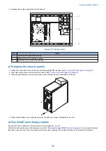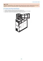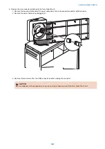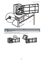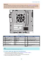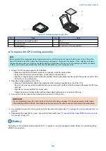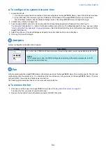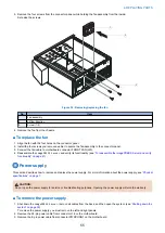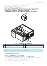
2. Install the motherboard in the chassis.
Angle the motherboard so that the motherboard connectors fit into the cutouts in the back of the chassis.
IMPORTANT:
Make sure that the flexible grounding tabs on the cutouts for the network ports make contact with the outside of the ports.
Do not allow the tabs to fold over or become bent inside the ports. The ports will not function if the tabs are placed improperly.
Take care when lowering the new motherboard into the chassis. Do not strike the motherboard against the metal standoffs
attached to the chassis, as doing so can damage the components on the underside of the motherboard.
3. Align the mounting holes on the motherboard with the standoffs located in the base of the chassis.
4. Secure the motherboard to the chassis using all the mounting screws that you removed earlier.
Partially tighten each screw before completing tightening any one screw. Do not overtighten the screws; doing so could
damage traces on the motherboard.
You are now ready to complete motherboard installation.
● To replace boards, cables, and components
1. Replace the hard disk drive bracket, with hard disk drive attached (see
“To replace the hard disk drive” on page 59
)
You removed the hard disk drive bracket to provide clearance for removing the motherboard.
2. Replace the following cables (see
“Removing the motherboard” on page 42
• CPU fan cable
• 24-pin motherboard power cable
• 8-pin x 2 motherboard power cable
• Fiery QuickTouch power/LED cable
• Fiery QuickTouch USB port cable
• Hard disk drive cable
• SATA data cable
• Power supply cable
• DVD drive cables:
• Power and data combination cable
• SATA data cable
• Rear fan cable
3. Secure cables as necessary with any plastic cable clamp that you may have removed earlier.
4. Replace the printer interface board (see
“Removing the motherboard” on page 42
Make sure to install the board mounting bracket screw to secure the board to the chassis. Press down firmly on the top of
the board as you insert the screw.
IMPORTANT:
Make sure that unused connector panel slots are covered with slot covers. Uncovered slots reduce air flow and may cause
the
imagePRESS Server
to overheat.
5. If you reinstalled the old motherboard, reassemble the
imagePRESS Server
and verify its functionality. (see
the imagePRESS Server and verify functionality” on page 61
6. If you replaced the motherboard with a new motherboard, do the following:
• Remove the battery (see
• Wait two minutes to allow the motherboard electrical components to fully discharge.
• Reinstall the battery.
• Reassemble the
imagePRESS Server
“To reassemble the imagePRESS Server and verify functionality” on page
)
• Reset the time and date in Setup (see
“To configure the system date and time” on page 54
)
Verifying new motherboard installation, and transferring options and
BIOS information
After you install a new motherboard and reassemble the system, do the following:
4. REPLACING PARTS
46
Summary of Contents for ImagePRESS Server H350 V2
Page 8: ...Introduction 1 Introduction 2 Specifications 7 ...
Page 17: ...INSTALLING HARDWARE 2 Installing Hardware 11 ...
Page 26: ...USING THE IMAGEPRESS SERVER 3 Using the imagePRESS Server 20 ...
Page 35: ...REPLACING PARTS 4 Replacing parts 29 ...
Page 86: ...INSTALLING SYSTEM SOFTWARE 6 Installing System Software 80 ...
Page 91: ...TROUBLESHOOTI NG 7 Troubleshooting 85 ...
Page 104: ...INSTALLATION PROCEDURE 8 Installation 98 Removable HDD Kit B5 108 ...

