background image

4

4

Installation Procedure

Installation Procedure

Installation Procedure


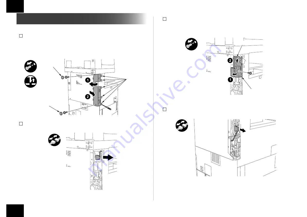
Installing the Open I/F PCB

1) Remove the Left Rear Cover.
•  2 Rubber Caps
•  2 Screws
•  5 Claws

x2

x5

Claws

Rubber Caps

Rubber Caps

2) When the Reader is installed, remove the Reader Communication Cable.

F-1-6

F-1-7

3) Remove the Left Rear Sub Cover.
•  1 Screw
•  1 Hook

Hook

Left Rear 

Sub Cover

4) When the FAX is installed, remove the FAX cable.

F-1-8

F-1-9

Summary of Contents for imagePASS-B2

Page 1: ...glish These procedures are different from each other Follow the procedure corresponding to the installed model Japanese The installation procedure for Japan model English The installation procedure for the other models except for Japan model この設置手順書には 和文と英文の設置手順が記載されている 和文では日本モデル用の設置手順が記載されており 英文では日本モデル以外のその他のモデル用の設 置手順が記載されている それぞれの設置手順は異なっているので モデルに応じた手順に従うこと 和文 日本モデル用設置手順 英文 日本モデル以外のその他のモデル用設置手...

Page 2: ...ual Check Claw Remove Checking instruction F 1 1 F 1 2 Before Connection The IP addresses for communication between the host machine and server are set automatically 1 Enter the Service Mode level 1 2 COPIER OPTION INT FACE IMGCONT 3 3 Exit the Service Mode Securing space for installation Secure a space to install this equipment as shown in the figure below A space of 200mm or more is required fro...

Page 3: ... I F PCB X 1 9 Screw TP M3x6 X 4 10 Screw with Toothed Washer Binding small M4x8 X 8 11 Stepped Screw M4 X 4 12 Wire Saddle X 3 F 1 4 4 Power Cord The connector has a different shape depending on locations 2 are packaged in the products for EUR 1 is packaged in the products for USA Use the correct power code to mach the location area of installation Make sure not to leave unused power code at the ...

Page 4: ...move the Left Rear Cover 2 Rubber Caps 2 Screws 5 Claws x2 x5 Claws Rubber Caps Rubber Caps 2 When the Reader is installed remove the Reader Communication Cable F 1 6 F 1 7 3 Remove the Left Rear Sub Cover 1 Screw 1 Hook Hook Left Rear Sub Cover 4 When the FAX is installed remove the FAX cable F 1 8 F 1 9 ...

Page 5: ...crews are not used NOTE Ask the user to store the Face Cover and Screws in case it is needed in the future x2 F 1 10 F 1 11 7 Remove the 2 screws the removed screws are used in step 9 x2 8 Remove the Bypass PCB the removed Bypass PCB is not used 2 Screws the removed screws are not used NOTE Ask the user to store the Bypass PCB and Screws in case it is needed in the future x2 F 1 12 F 1 13 ...

Page 6: ...screws Make sure to tilt the grip slowly on both sides simultaneously Check that the Main Controller PCB 2 is installed properly x2 Grip F 1 14 F 1 15 11 Install the FAX Cable if the FAX is installed 12 Install the Left Rear Sub Cover 1 Screw 13 Install the Reader Communication Cable if the Reader is installed 14 Connect the Interface Cable to the installed Open I F PCB 15 Cut off A part of the Le...

Page 7: ... Install the 2 Support Plates 4 Stepped Screws M4 4 Screws with Toothed Washers Binding M4x8 Screws with Toothed Washer Screws with Toothed Washer Stepped Screw Stepped Screw x8 F 1 18 F 1 19 3 Remove the 4 Screws 4 Install the Mounting Plate with the removed screws CAUTION Be sure to install it in the correction direction x4 x4 Slot Hole Slot Hole 5 Install the PS Unit in the direction of the arr...

Page 8: ...e 3 Wire Saddles 10 Connect the Power Cord and the Shield Ethernet Cable to the PS Unit 11 Secure the cables in place using the 3 Wire Saddle as shown in the figure below CAUTION Use the correct power code to mach the location area of installation Make sure not to leave unused power code at the site Be sure to use the network cable with Category 5e or higher In addition a sealed type STP cable is ...

Page 9: ...assword input screen is displayed Entering Fiery 1 in the password field displays the setting screen NOTE Use single byte upper case to enter F of Fiery 1 Use single byte lower case to enter other characters In response the machine will automatically show the Settings menu Be sure to at least select the following and make the appropriate settings in the indicated order Server Setup Network Setup a...

Page 10: ... including port protocol and service F 1 28 F 1 29 Making Printer Settings Make the appropriate settings including print queue 4 Select close on the Settings menu In response the system will restart automatically Checking the Operation After Making the Settings Print out a test page and a settings page as follows to make sure that all settings have correctly been made on the equipment and its host...

Page 11: ...Settings 3 Make the following selections on the control panel Function Print page Test Page Configuration F 1 32 F 1 33 Connecting to the Network Ask the network administrator to connect to the network make settings and output the test print Refer to Settings Management in User Manual for details of checking work F 1 34 F 1 35 ...

Page 12: ...てシンボルマークで表現している コネクタ 取付け ビス 取付け 取外し 取外し 取外し 取付け 束線 押す 取外し コンセント 差込み スイッチON 音確認 確認 目視 爪 取付け F 1 1 F 1 2 接続前の準備 本体と本機間の通信用 IP アドレスを自動で設定する 1 サービスモード レベル 1 に入る 2 COPIER OPTION INT FACE IMG CONT を選択し 3 を登録する 3 サービスモードから抜ける 設置するスペースを確保する 図のように本機を設置するスペースを確保する 本機の背面から 200mm 以上のスペースが 必要である 200 mm以上 背面 本機 前面 本体主電源 OFF の確認事項 本体の主電源が OFF であることを確認する 1 本体の主電源スイッチを OFF する 2 操作パネルの表示と主電源ランプが消えたことを確認してから電源プラグを外す...

Page 13: ...ニット X 1 2 PSユニット固定板 X 1 3 支持板 X 2 4 電源コード X 1 5 クロスイーサネット ケーブル 0 5m X1 6 シールドイーサネット ケーブル 3m X1 7 インターフェイス ケーブル X 1 8 オープンI F基板 X 1 9 ビス TP M3x6 X 4 10 歯付き座金付ビス バインド M4 8 X 8 11 段ビス M4 X 4 12 ワイヤサドルX 3 CD ガイド類 メディアパック F 1 4 取付け概略図 F 1 5 ...

Page 14: ...付け 設置手順 オープン I F 基板の取付け 設置手順 オープン I F 基板の取付け 1 左奥カバーを外す ゴムキャップ 2 個 ビス 2 本 爪 5 箇所 x2 x5 爪 ゴムキャップ ゴムキャップ 2 リーダーが付いている場合は リーダー通信ケーブルを外す F 1 6 F 1 7 3 左奥サブカバーを外す ビス 1 本 フック 1 箇所 フック 左奥サブカバー 4 FAX が付いている場合は FAX のケーブルを外す F 1 8 F 1 9 ...

Page 15: ...持ち メインコントローラー基板 2 を外す ビス 2 本 x2 取っ手 6 目隠し板を外す 外した目隠し板は使用しない ビス 2 本 外したビスは使用しない メモ 外した目隠し板とビスはユーザーに渡し 保管して頂くこと x2 F 1 10 F 1 11 7 ビス 2 本を外す 外したビスは手順 9 で使用する x2 8 バイパス基板を外す 外したバイパス基板は使用しない ビス 2 本 外したビスは使用しない メモ 外したバイパス基板とビスはユーザーに渡し 保管して頂くこと x2 F 1 12 F 1 13 ...

Page 16: ...ーラー基板 2 を取付ける 注意 取っ手を持上げてメインコントローラー基板 2 を差込み 突き当ったら取っ手を倒し てビス 2 本で取付けること 取っ手を倒す際はゆっくり倒すこと メインコントローラー基板 2 が 確実に装着されていることを確認すること x2 取っ手 F 1 14 F 1 15 11 FAX のケーブルを取付ける FAX が付いている場合 12 左奥サブカバーを取付ける ビス 1 本 13 リーダー通信ケーブルを取付ける リーダーが付いている場合 14 取付けたオープン I F 基板にインターフェイスケーブルを取付ける 15 左奥カバーの A 部分をニッパー等で切る 注意 バリが出ないように切取ること A F 1 16 F 1 17 ...

Page 17: ... 個 PS ユニットの取付け 1 後カバーの目隠しシール 9 枚を外す 剥した目隠しシールは使用しない 2 支持板 2 個を取付ける 段ビス M4 4 本 歯付き座金付ビス バインド M4x8 4 本 歯付き座金付ビス 歯付き座金付ビス 段ビス 段ビス x8 F 1 18 F 1 19 3 ビス 4 本を外す 4 外したビスで PS ユニット固定板を取付ける 注意 取付ける向きを間違えないこと x4 x4 長穴 長穴 5 PS ユニットを矢印方向に取付ける 歯付き座金付ビス バインド M4x8 4 本 x4 F 1 20 F 1 21 ...

Page 18: ...1 箇所 x2 クロスイーサ ネットケーブル インターフェイス ケーブル 8 右奥カバー 1 を閉める F 1 22 9 ワイヤサドル 3 個を取付ける 10 電源コードとシールドイーサネットワークケーブルを PS ユニットに取付ける 11 下図のようにケーブルをワイヤサドル 3 箇所で固定する 注意 ネットワークケーブルは カテゴリ 5e 以上のランクのものを使用すること また シー ルドタイプ STP ケーブル の使用を推奨する ノンシールドタイプ UTP ケーブル を 使用すると ネットワークケーブルを経由して 周りの電子機器に影響を及ぼす可能性 がある x2 x3 シールドイーサ ネットケーブル 電源コード F 1 23 F 1 24 ...

Page 19: ...サーバー を選択する 2 プリントサーバーの状況 設定 ボタンを押す F 1 25 F 1 26 パスワードの入力 設置時にパスワード入力画面が表示される パスワード欄に Fiery 1 を入力する と設定画面が表示される メモ Fiery 1 の F は半角大文字で入力する それ以外は半角小文字で入力する その後 自動的に 設定 メニューに入るので最低 サーバ設定 ネットワーク設定 プ リンタ設定 の各項目を順番に選択し 各々データを保存する 詳細は 取扱説明書の 設 定管理 を参照する 例えば サーバ設定 の各項目を設定していくと 最後に変更の保存をするかどうかを選 択する画面が表示されるので はい を選択すると その時の設定を保存することができる 各項目を順番に選択して保存しないと次の項目を設定できない F 1 27 ...

Page 20: ...認 サーバ設定 サーバ名の設定等を行う ネットワーク設定 ポート設定 プロトコル設定 サービス設定を行う F 1 28 F 1 29 プリンタ設定 印刷キューの設定を行う 3 設定 メニューの 閉じる を選択する その後 自動的に再起動が行われる 設定後の動作確認 以下の手順で テストページ 設定ページを出力し 接続機器と本機の接続および本機の 設定を確認する 1 接続機器の液晶表示部上のメインメニューから プリントサーバー を選択する F 1 30 F 1 31 ...

Page 21: ...21 21 設置手順 ネットワークへの接続 設置手順 ネットワークへの接続 2 プリントサーバーの状況 設定 ボタンを押す 3 機能 ページの印刷 テストページ および 設定ページ を選択する F 1 32 F 1 33 ネットワークへの接続 ネットワーク管理者にネットワークへの接続 設定およびテストプリントを依頼する 確認作業は 取扱説明書の 設定管理 を参照して行う F 1 34 F 1 35 ...

Page 22: ......

Page 23: ......

Page 24: ......

Reviews: