background image

4

4

Installation Procedure > In the case iR-ADV C5255/C5250/C5240/C5235 Series > Installing the Open I/F PCB

Installation Procedure > In the case iR-ADV C5255/C5250/C5240/C5235 Series > Installing the Open I/F PCB

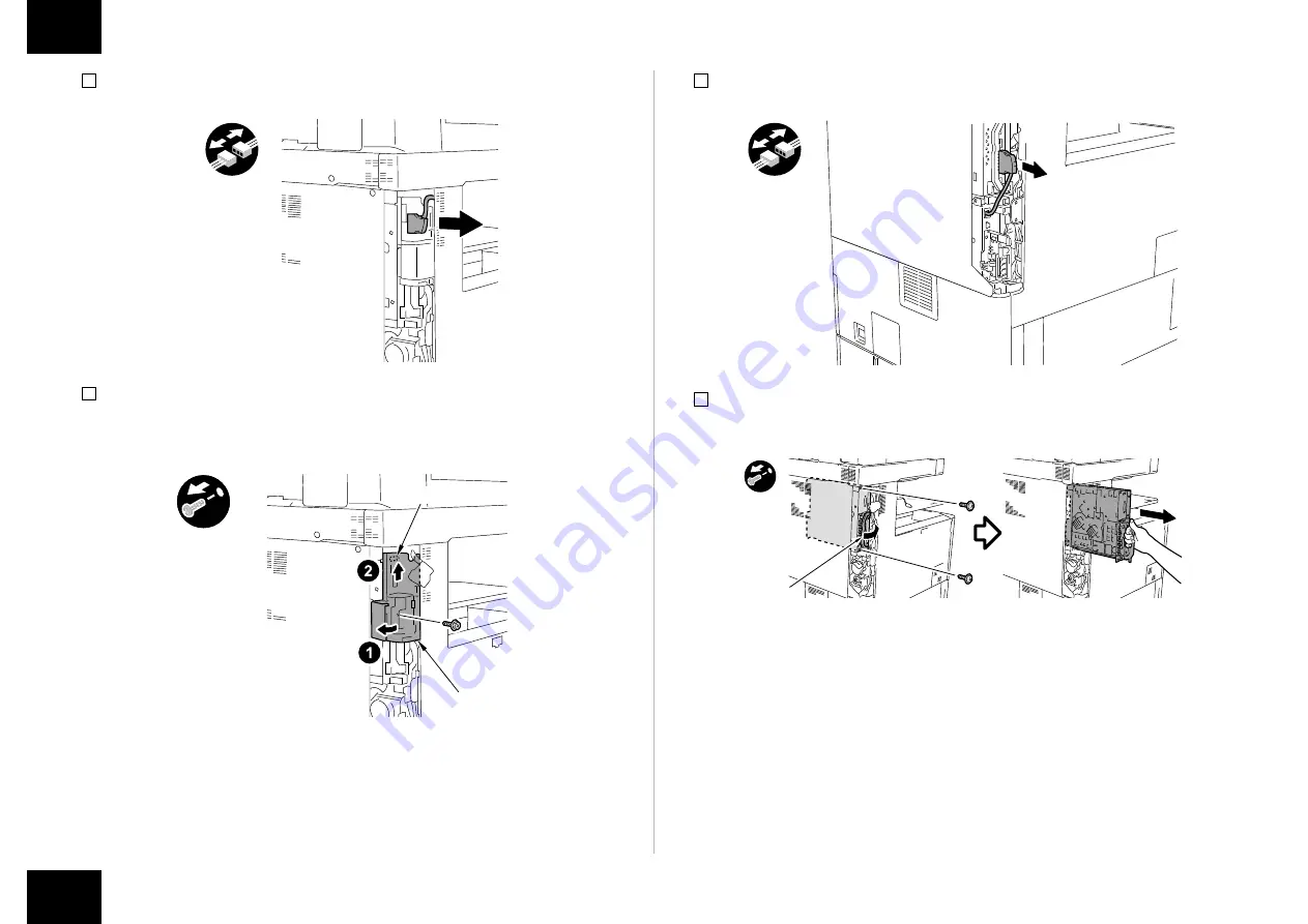
2) When the Reader is installed, remove the Reader Communication Cable.

3) Remove the Left Rear Sub Cover.
•  1 Screw
•  1 Hook

Hook

Left Rear 

Sub Cover

F-1-6

F-1-7

4) When the FAX is installed, remove the FAX cable.

5) Hold the handle to remove Main Controller PCB 2.
•  2 Screws

x2

Grip

F-1-8

F-1-9

Summary of Contents for ColorPASS-GX400

Page 1: ...n English These procedures are different from each other Follow the procedure corresponding to the installed model Japanese The installation procedure for Japan model English The installation procedure for the other models except for Japan model この設置手順書には 和文と英文の設置手順が記載されている 和文では日本モデル用の設置手順が記載されており 英文では日本モデル以外のその他のモデル用の設 置手順が記載されている それぞれの設置手順は異なっているので モデルに応じた手順に従うこと 和文 日本モデル用設置手順 英文 日本モデル以外のその他のモデル...

Page 2: ...crew Tighten Remove Connect Secure Free Harness Push Insert Plug in Turn on Sound Check Check Visual Check Claw Remove Checking instruction F 1 1 F 1 2 Before Connection The IP addresses for communication between the host machine and server are set automatically 1 Enter the Service Mode level 1 2 Select COPIER OPTION INT FACE IMG CONT 3 3 Exit the Service Mode Securing space for installation Secur...

Page 3: ...ding on locations Use the correct power code to mach the location area of installation Make sure not to leave unused power code at the site CD Guides Media Pack Check Items when Turning OFF the Main Power Check that the main power switch is OFF 1 Turn OFF the main power switch of the host machine 2 Be sure that display in the Control Panel and the lamp of the main power supply are turned off then ...

Page 4: ...ADV C5255 C5250 C5240 C5235 Series Installing the Open I F PCB 2 When the Reader is installed remove the Reader Communication Cable 3 Remove the Left Rear Sub Cover 1 Screw 1 Hook Hook Left Rear Sub Cover F 1 6 F 1 7 4 When the FAX is installed remove the FAX cable 5 Hold the handle to remove Main Controller PCB 2 2 Screws x2 Grip F 1 8 F 1 9 ...

Page 5: ...oved screws are used in step 9 NOTE Ask the user to store the Face Cover in case it is needed in the future x2 7 Remove the 2 screws the removed screws are used in step 9 x2 F 1 10 F 1 11 8 Remove the Bypass PCB the removed Bypass PCB is not used 2 Screws the removed screws are used in step 9 NOTE Ask the user to store the Bypass PCB in case it is needed in the future x2 9 Install the Open I F PCB...

Page 6: ...th sides simultaneously Check that the Main Controller PCB 2 is installed properly x2 Grip 11 Install the FAX Cable if the FAX is installed 12 Install the Left Rear Sub Cover 1 Screw 13 Install the Reader Communication Cable if the Reader is installed 14 Connect the Interface Cable to the installed Open I F PCB F 1 14 F 1 15 15 Cut off A part of the Left Rear Cover with nippers CAUTION Be sure to ...

Page 7: ... code at the site Be sure to use the network cable with Category 5e or higher In addition a sealed type STP cable is recommended When using the non sealed type UTP cable it may influence the surrounding electronic equipments via network cable x2 Power Cord Shield Ethernet Cable 6 Plug the power cord into an outlet 7 Turn the PS Unit power on then turn the host machine power switch on 8 When the me...

Page 8: ...Installing the Open I F PCB 1 Remove the Box Left Cover 2 Screws the removed screws are used in step 12 x2 2 Disconnect the Reader Communication Cable and release the 2 Lock Levers Lock Lever Reader Communication Cable F 1 21 F 1 22 3 Hold the grip to remove Main Controller PCB 2 2 screws the removed screws are used in step 9 Grip x2 4 Remove the Face Cover Removed Face Cover is not used 2 Screws ...

Page 9: ...ss PCB Removed Bypass PCB is not used 2 Screws the removed screws are used in step 7 1 Connector NOTE Ask the user to store the Bypass PCB and Screws in case it is needed in the future x2 Connector F 1 25 F 1 26 7 Install the Open I F PCB 1 Connector 6 Screws the screws removed in step 4 5 and 6 x2 x4 Connector 8 Release the 2 Lock Levers in the direction of the arrow and push the Main Controller ...

Page 10: ...PCB 9 Turn over the 2 Lock Levers push the Main Controller PCB 2 in and fix it 2 Screws screw removed in step 3 Install the upper one first and then the lower one CAUTION Reliable work in order from Figure 1 to 4 should be done in case of no connection regarding Main Controller PCB 2 Lock Lever x2 10 Disconnect the Reader Communication Cable F 1 29 11 Connect the Interface Cable to the Open I F PC...

Page 11: ...PRO Series iR ADV C7280 C7270 C7260 Series Installing the PS Unit Installing the PS Unit 1 Install the PS Unit to the left side of the host machine 2 Connect the Interface Cable to the PS Unit F 1 32 F 1 33 3 Open the HDD Cover connect one end of the Crossover Ethernet Cable to the host machine and then connect another end to the PS Unit Cross Ethernet Cable 4 Close the HDD Cover F 1 34 ...

Page 12: ...ry 5e or higher In addition a sealed type STP cable is recommended When using the non sealed type UTP cable it may influence the surrounding electronic equipments via network cable x2 Power Cord Shield Ethernet Cable F 1 35 6 Plug the power cord into an outlet 7 Turn the PS Unit power on then turn the host machine power switch on 8 When the message Turn the host machine power off and back on appea...

Page 13: ...r F of Fiery 1 Use single byte lower case to enter other characters In response the machine will automatically show the Settings menu Be sure to at least select the following and make the appropriate settings in the indicated order Server Setup Network Setup and Printer Setup For more information see Settings Management on the User Manual For instance once you have made the various settings under ...

Page 14: ...luding the name of the server Making Network Settings Make the appropriate settings including Port Setup Protocol Setup and Service Setup F 1 39 F 1 40 Making Printer Settings Make the appropriate settings including print queue 4 Select close on the Settings menu In response the system will restart automatically F 1 41 ...

Page 15: ... the Settings Print out a test page and a settings page as follows to make sure that all settings have correctly been made on the equipment and its host machine and that all connections are normal 1 At the Main menu press Printer 2 Press Print Server Status Settings F 1 42 F 1 43 3 Make the following selections on the control panel Functions Print page Test Page and Configuration F 1 44 F 1 45 ...

Page 16: ...ement in User Manual for details of checking work Executing Auto Gradation Adjustment After installation execute Auto Gradation Adjustment on the host machine If the Color Image Reader is installed in the host machine perform Auto Gradation Adjustment Full Adjust with Plain Paper Heavy 1 Heavy 2 and Heavy 3 Heavy 4 If the Color Image Reader does not exist in the host machine execute Settings Regis...

Page 17: ...く行う動作などについてシンボルマークで表現している コネクタ 取付け ビス 取付け 取外し 取外し 取外し 取付け 束線 押す 取外し コンセント 差込み スイッチON 音確認 確認 目視 爪 取付け F 1 1 F 1 2 接続前の準備 本体と本機間の通信用 IP アドレスを自動で設定する 1 サービスモード レベル 1 に入る 2 COPIER OPTION INT FACE IMG CONT 3 を選択する 3 サービスモードから抜ける 設置するスペースを確保する 図のように本機を設置するスペースを確保する 本機の背面から 200 mm 以上のスペースが 必要である 背面 200mm 8 in 200mm 8 in PSユニット 前面 Top view 事前に準備するもの マウス モニター キーボード F 1 3 ...

Page 18: ...3 0m X1 CD ガイド類 メディアパック 本体主電源 OFF の確認事項 本体の主電源が OFF であることを確認する 1 本体の主電源スイッチを OFF する 2 操作パネルの表示と主電源ランプが消えたことを確認してから電源プラグを外す F 1 4 設置手順 iR ADV C9280 PRO C9270 PRO シリーズ iR ADV C7280 C7270 C7260 シリーズ オープン I F 基板の取付け 1 ボックス左カバーを外す ビス 2 本 外したビスは手順 12 で使用する x2 2 リーダー通信ケーブルを外し ロックレバー 2 箇所を解除する ロックレバー リーダー通信ケーブル F 1 5 F 1 6 ...

Page 19: ...は手順 9 で使用する 取っ手 x2 4 目隠し板を外す 外した目隠し板は使用しない ビス 2 本 外したビスは手順 7 で使用する メモ 外した目隠し板はユーザーに渡し 保管して頂くこと x2 F 1 7 5 ビス 2 本を外す 外したビスは手順 7 で使用する x2 6 バイパス基板を外す 外したバイパス基板は使用しない ビス 2 本 外したビスは手順 7 で使用する コネクタ 1 箇所 メモ 外したバイパス基板はユーザーに渡し 保管して頂くこと x2 コネクタ F 1 8 F 1 9 ...

Page 20: ...箇所を矢印の方向に解除し メインコントローラー基板 2 を突き当たるまで 両手で均等に押込む 注意 ケーブル類をはさみこまないように注意して メインコントローラー基板 2 を取付ける ロック レバー F 1 10 F 1 11 9 ロックレバー 2 個を倒して さらにメインコントローラー基板 2 を押込み 固定する ビス 2 本 手順 3 で外したビス 下 上の順に取付ける 注意 メインコントローラー基板 2 のコネクタが接続されていない場合があるため 図の 1 4 の順番で確実に作業を行うこと ロック レバー x2 10 リーダー通信ケーブルを接続する F 1 12 ...

Page 21: ...21 21 11 オープン I F 基板にインターフェースケーブルを接続する 注意 FAX のコネクタには接続しないこと F 1 14 F 1 13 12 インターフェースケーブルをボックス左カバーの穴に通して ボックス左カバーを取付ける ビス 2 本 手順 1 で外したビスを使用する x2 穴 F 1 15 ...

Page 22: ...22 22 PS ユニットの設置 1 PS ユニットを本体左側に設置する 2 PS ユニットにインターフェースケーブルを取付ける F 1 16 F 1 17 3 HDD カバーを開き クロスイーサネットケーブルを本体と PS ユニットに接続する クロスイーサネットケーブル 4 HDD カバーを閉める F 1 18 ...

Page 23: ...奨する ノンシールドタイプ UTP ケー ブル を使用すると ネットワークケーブルを経由して 周りの電子機器に影響を及ぼ す可能性がある x2 電源コード シールドイーサネットケーブル F 1 19 6 電源プラグをコンセントに差込む 7 PS ユニットの電源を ON した後 本体の主電源スイッチを ON する 8 タッチパネル上に 本体の主電源を入れ直してください と表示したら 本体の主電源ス イッチを OFF する メモ PS ユニットは 接続した初回だけ自動的に再起動する 使用可能になるまで約 5 分かかる 使用可能になるまで PS ユニットのボタンを押さないこと 9 再び 本体の主電源スイッチを ON する ...

Page 24: ...パスワード入力画面が表示される パスワード欄に Fiery 1 を入力すると設定画面が表示される メモ Fiery 1 の F は半角大文字で入力する それ以外は半角小文字で入力する その後 自動的に 設定 メニューに入るので最低 サーバ設定 ネットワーク設定 プリンタ設定 の各項目を順番に選択し 各々データを保存する 詳細は 取扱説明書の 設定管理 を参照する 例えば サーバ設定 の各項目を設定していくと 最後に変更の保存をするかどうかを 選択する画面が表示されるので はい を選択すると その時の設定を保存することが できる 各項目を順番に選択して保存しないと次の項目を設定できない F 1 22 ...

Page 25: ...25 25 サーバー設定 サーバー名の設定等を行う ネットワーク設定 ポート設定 プロトコル設定 サービス設定を行う F 1 23 F 1 24 プリンタ設定 印刷キューの設定を行う 3 設定 メニューの 閉じる を選択する その後 自動的に再起動が行われる F 1 25 ...

Page 26: ...26 26 設定後の動作確認 以下の手順で テストページ 設定ページを出力し 接続機器と本機の接続および本機の 設定を確認する 1 接続機器の液晶表示部上のメインメニューから プリントサーバー を選択する 2 プリントサーバーの状況 設定 ボタンを押す F 1 26 F 1 27 3 機能 ページの印刷 テストページ および 設定ページ を選択する F 1 28 F 1 29 ...

Page 27: ...管理者にネットワークへの接続 設定およびテストプリントを依頼する 確認作業は 取扱説明書の 設定管理 を参照して行う 自動階調補正の実施 設置時には 本体の自動階調補正を行う 本体にカラーイメージリーダーが装着されている場合は 普通紙 と 厚紙 1 厚紙 2 と 厚紙 3 厚紙 4 で自動階調補正 フル補正 を必ず行うこと 本体にカラーイメージリーダーが無い場合は 設定 登録 調整 メンテナンス 画 質調整 自動階調補正 を実行する F 1 30 ...

Page 28: ......

Reviews: