


CHAPTER 2 STANDARDS AND ADJUSTMENTS
2-35P
3) Select the PCB in question, and click ‘Start to Connect’.
S-CON:
DIMM for system controller PCB
DC-CON:
DIMM for DC controller PCB
4) Download the data for the flash ROM by going through the instructions appearing on
the PC screen.
Do not turn off the machine or the PC during downloading; such could put
the DIMM out of order, rendering it unusable.
5) When downloading has ended, turn off the PC as follows:
‘OK’
→
‘Return to Main Menu’
→
‘End Copier Service Support Tool’
→
‘End’
c. After Downloading
1) Turn off the main power switch, and disconnect the power plug.
2) Disconnect the bi-Centronics cable from the printer unit.
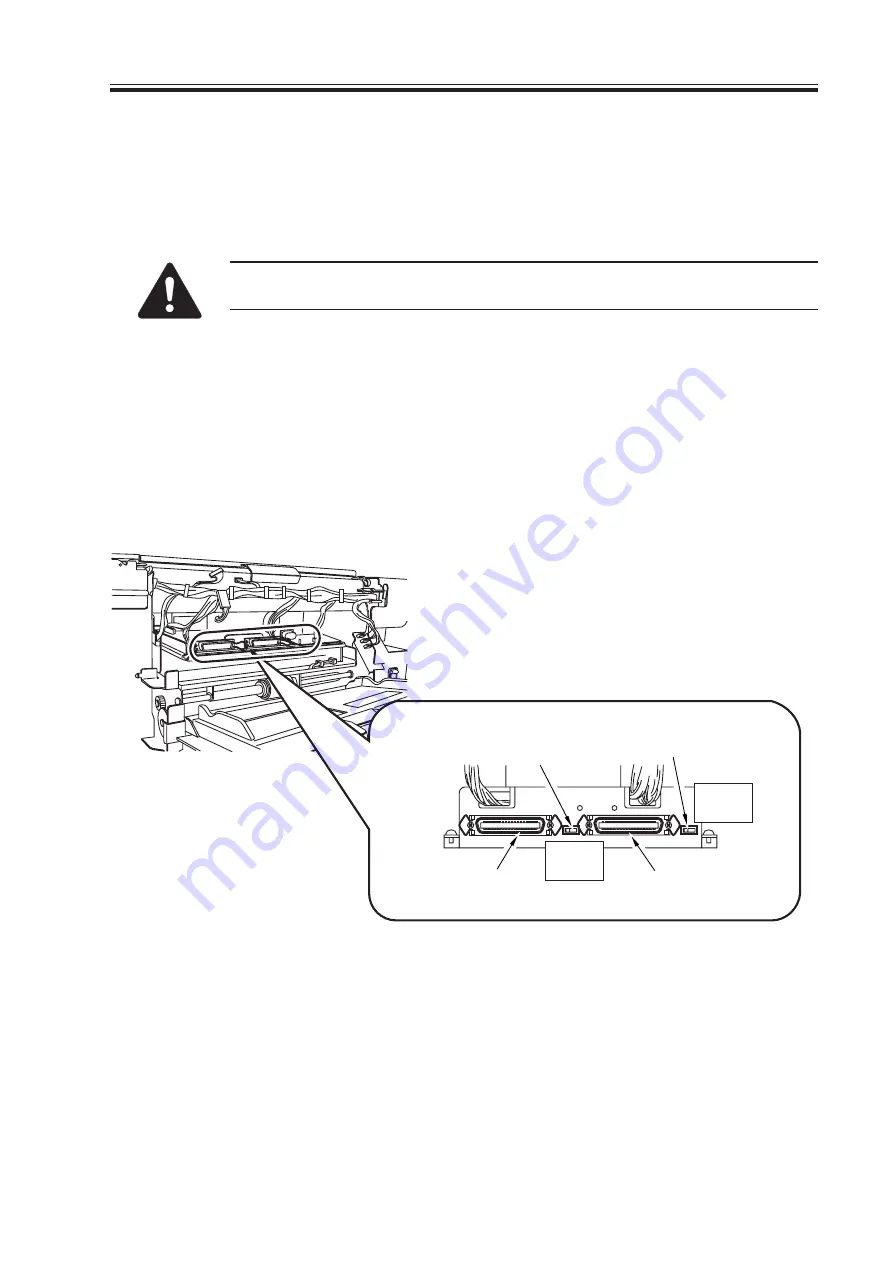
3) Slide the download switch to the COPY position.
F02-702-03
Download switch
(for system controller PCB)
Download connector
(for system controller PCB)
Download connector
(for DC controller PCB)
Download switch
(for DC controller PCB)
←
COPY
→
LOAD
←
COPY
→
LOAD
Summary of Contents for C2050
Page 4: ...i i INTRODUCTION ...
Page 12: ......
Page 36: ......
Page 44: ......
Page 45: ...APPENDIX ...
Page 46: ......
Page 52: ......
Page 53: ...Printer Unit COPYRIGHT 2000 CANON INC 2000 CANON C2050 2020 C2100 2100S REV 0 NOV 2000 ...
Page 54: ......
Page 101: ...CHAPTER 3 ARRANGEMENT AND FUNCTIONS OF ELECTRICAL PARTS 3 5P 2 Thermistor Lamps and Heaters ...
Page 121: ...APPENDIX ...
Page 122: ......
Page 132: ...A 10P APPENDIX ...
Page 134: ......
Page 136: ......
Page 140: ......
Page 141: ...Service Mode COPYRIGHT 2000 CANON INC 2000 CANON C2050 2020 C2100 2100S REV 0 NOV 2000 ...
Page 142: ......
Page 160: ...SERVICE MODE S 18 COPIER DISPLAY G Indicates the location 0 machine 1 feeder 2 finisher ...
Page 262: ......
Page 263: ...Error Code COPYRIGHT 2000 CANON INC 2000 CANON C2050 2020 C2100 2100S REV 0 NOV 2000 ...
Page 264: ......


