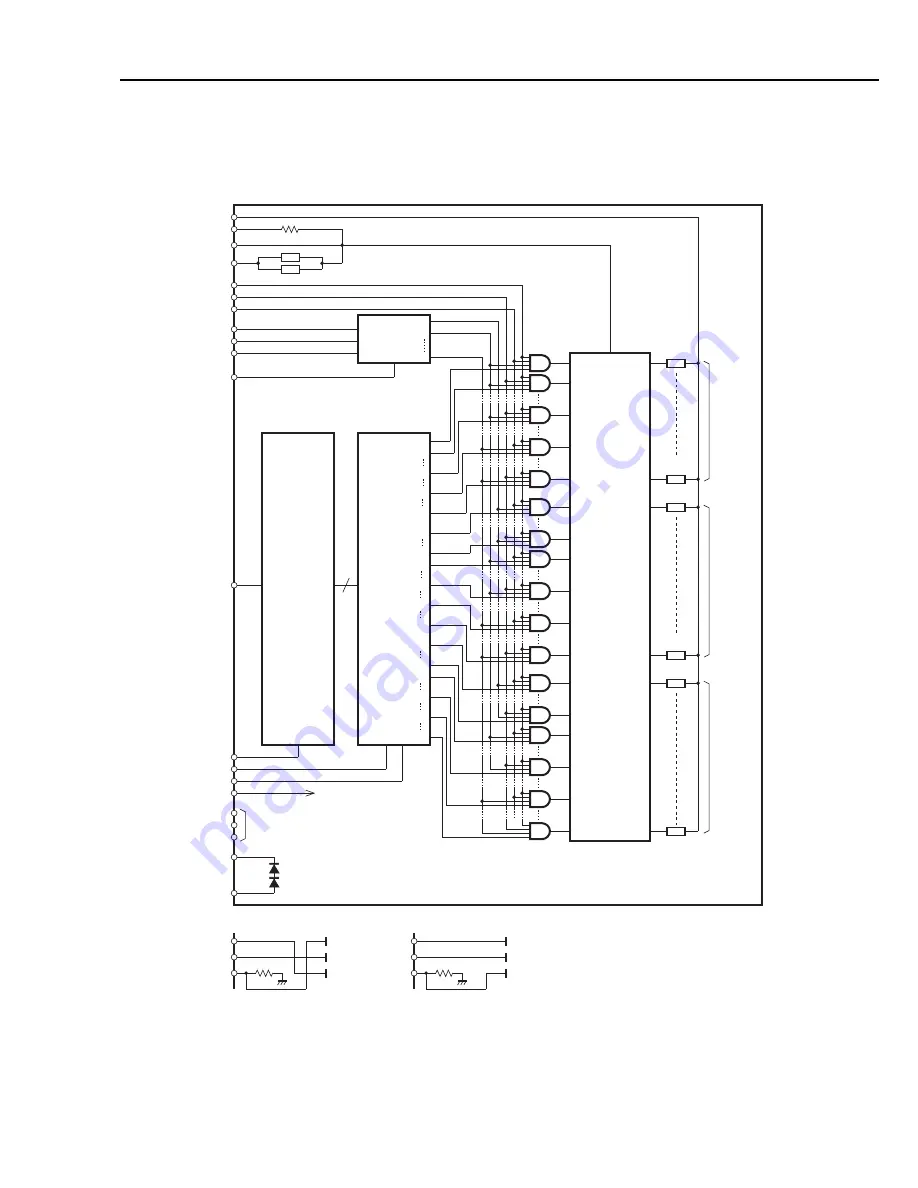
2) BC-61 and BC-62e Photo
The color head and photo head are equipped with the drive circuit shown in Figure
4-22.
4-25
BJC-7100
Part 4: Technical Reference
1
2
6
61
80
81
102
157
160
161
180
181
198
235
240
84
85
1
2
6
Block
Enable
Decoder
1
240-bit
Latch
2
6
61
80
81
84
85
102
157
160
161
180
181
198
235
240
240-bit
Shift Register
240
See diagrams below.
Head Temperature Sensor
Rank Resistance
Sub-heater
VDDH
VH
RANK
GND
SUBH
HEATE
ODDE
EVENE
BE0
BE1
BE2
INV
IDATA
DCLK
LTRST
VDDH
EL
ID1
ID2
TSK
TSA
LTCLK
240-bit
Transistor Array
Heater
240
Heater
1
EL
ID1
ID2
Yellow
Color Head
EL
ID1
ID2
Yellow
Photo
Magenta
Magenta
Cyan
Cyan
Contact
Contact
Heater
80
Heater
81
Heater
160
Heater
161
Yellow
(80 nozzles)
Magenta
(80 nozzles)
Cyan
(80 nozzles)
Figure 4-22 Block Diagram of BC-61/BC-62e Photo Drive Circuit
Summary of Contents for BJC-7100
Page 2: ...1098 AB 5 00 0 ...
Page 3: ......
Page 14: ......
Page 16: ......
Page 32: ...Part 1 Safety and Precautions BJC 7100 1 16 This page intentionally left blank ...
Page 34: ......
Page 54: ......
Page 80: ......
Page 130: ...Part 4 Technical Reference BJC 7100 4 50 This page intentionally left blank ...
Page 132: ......
Page 178: ...Part 5 Maintenance BJC 7100 5 46 This page intentionally left blank ...
Page 184: ......
Page 185: ...PRINTED IN JAPAN IMPRIME AU JAPON CANON INC The printing paper contains 70 waste paper ...


