iv
PREFACE
•
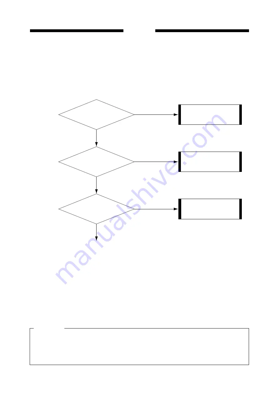
In order to remedy a problem, check the Steps in order. Answer the first "Check item"
question. If your answer matches that given in the "Result", follow the corresponding proce-
dure in the "Remedy" column. If your answer is not the same, go on to the next step and
repeat the same procedure.
•
When checking voltages using a tester is required, it will be specified in the check item.
For instance; "measure the voltage between J102-1 (+) and JI02-2 (-) on the engine control-
ler PCB". In this case, apply the plus and minus leads of the tester to the (+) and (-) termi-
nals indicated after the connector numbers:
e.g.
JI02-1 (+): Plus lead
JI02-2 (-): Minus lead
5. The signal address of the circuit diagram is shown by applicable pages of each controller
(indicated at the upper right of the circuit diagram) and its location.
CAUTION
Connect in the power code
to the machine and outlet.
Is the
power cord properly
connected to the receptacle
on the machine
and outlet?
YES
NO
1
<Remedy>
<Check item>
<Result>
<Step>
Explain to the customer that
the trouble is not attributable
to the machine.
Is the specified
voltage applied to the outlet?
YES
NO
2
Remove the cause of the
blown fuse and replace the
DC power PCB.
Is the fuse
on the DC power PCB (F1)
blown?
NO
YES
3
When checking voltages with a tester, touching the components or connector terminals on
the PCB with the hands may cause an electric shock. It is advisable to wear rubber gloves
or the like when power is supplied to the machine to protect yourself from electric shock.
iii
Summary of Contents for BJ-W3000
Page 2: ...0000 GR 0 40 0 ...
Page 3: ......
Page 12: ...ix PREFACE ...
Page 78: ...CHAPTER 2 BASIC OPERATION 2 21 ...
Page 124: ...CHAPTER 2 BASIC OPERATION 2 67 ...
Page 129: ...CHAPTER 3 MECHANICAL SYSTEM 3 4 ...
Page 266: ...APPENDIX MENU GUIDE A 1 ...
Page 268: ...PRINTED IN JAPAN IMPRIME AU JAPON CANON INC This document is printed on 100 recycled paper ...


