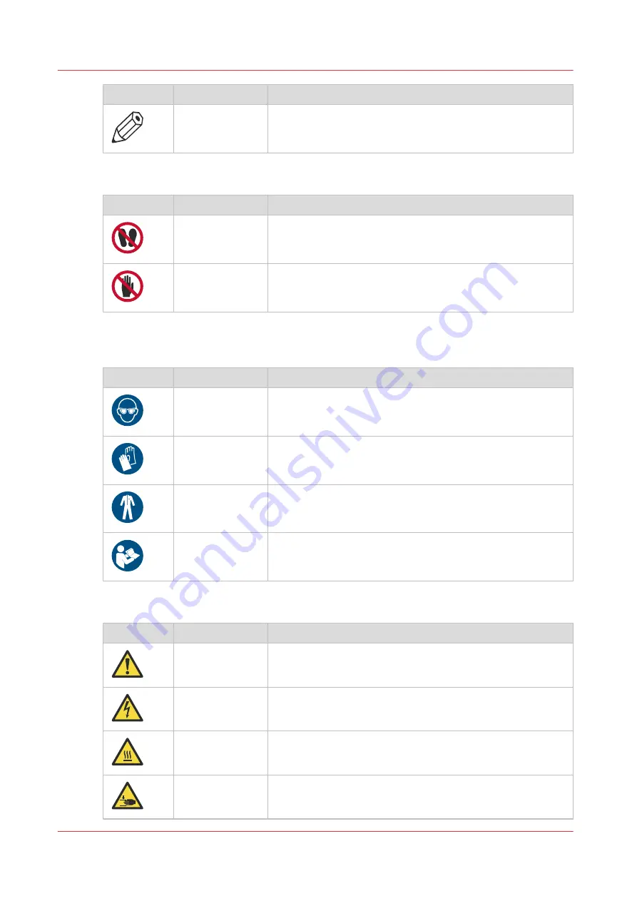
background image

Symbol

Type

Description

NOTE

Indicates a clarification of an operation or contains additional
explanations for a procedure. Reading these notes is highly
recommended.

If applicable the following Prohibited indicators are used in the User Documentation:

Label

Type

Description

PROHIBITED

Do not stand or walk in the indicated area.

PROHIBITED

Stay clear from the indicated area, when the equipment is
working.

If applicable the following Personal Protection indicators are used in the User Documentation

and or machine:

Symbol

Type

Description

Mandatory action Wear eye protection as prescribed in this document when

performing a task or action in this area.

Mandatory action Wear protecting gloves as prescribed in this document when

performing a task or action in this area.

Mandatory action Wear protection clothing as prescribed in this document

when performing a task or action in this area.

Mandatory action Read the user instruction manual/user documentation before

starting work or before operating equipment or machinery.

The following labels are used in the machine to identify and categorise the hazard level:

Label

Type

Description

Warning

General warning sign.

Warning

Electricity: Hazardous electrical voltage inside. Do not remove
the cover.

Caution

Hot surface: Take care to avoid direct contact with hot surfa-
ces.

Caution

Crushing of hands: Take care to avoid injury to hands when
in the vicinity of equipment with moving mechanical parts.

4

Safety and Environment Information

18

Chapter 2 - Safety Information

Summary of Contents for Arizona 135 GT

Page 1: ...Arizona 135 GT Operation guide 2021 2022 Canon Production Printing ...

Page 2: ...ions The content of this publication may be subject to changes from time to time without notice CANON PRODUCTION PRINTING SHALL NOT BE LIABLE FOR ANY DIRECT INDIRECT OR CONSEQUENTIAL DAMAGES OF ANY NATURE OR LOSSES OR EXPENSES RESULTING FROM THE USE OF THE CONTENTS OF THIS PUBLICATION Language Translation of the original instructions that are in American English Trademarks Canon is a registered tr...

Page 3: ...on software against cyber security threats Policy Guidelines Rules Canon s Secure Development Life Cycle SDLC process is an agile based development process that also models itself comparing with the National Institute of Standards and Technology NIST and Open Web Application Security Project aka OWASP It uses the practice of sprints to take advantage of the continuous delivery and flexibility that...

Page 4: ......

Page 5: ...l Module 44 Maintenance Tasks 51 Counters Module 52 Settings Module 54 Tools and Utilities Module 58 Software Update Module 61 Chapter 4 Operate the Printer 63 Training Requirements 64 Printer Power ON and Off 65 Print a Job 66 Manage the Table Vacuum 68 The Table Vacuum System 68 Using Vacuum Zones Metric Zones 70 Print the Metric Zone Map 70 Imperial Vacuum Zones 72 Batch Mode Printing 74 Enabli...

Page 6: ...ool 129 Create Spot Data in Photoshop 131 Prepare Spot Data in Adobe Illustrator 135 How to Overprint Spot Data in Illustrator 137 How to Place Raster Images in Illustrator 141 How to Create a Spot Channel Path in Illustrator 143 How to Set Up a File for Preflight s Spot Layer Tool 145 How to Name Your Spot Data in Illustrator 146 White Ink Quick Start 149 Print White Ink Jobs 151 Chapter 8 Ink Sy...

Page 7: ...ean the Rubber Capstan 200 Remove Stains 201 Remove Uncured Ink on the Capstan 203 Chapter 10 Troubleshooting and Support 207 Troubleshooting Overview 208 Enable the Remote Service connection 209 Configure remote assistance 212 Install software updates with Remote Service 213 Install software updates without Remote Service 215 Chapter 11 Regulation Notices 219 Appendix A Application Information 22...

Page 8: ...Contents 8 ...

Page 9: ...Chapter 1 Introduction ...

Page 10: ...cerning operations that may lead to death or injury to persons if not performed correctly To use the machine safely always pay attention to these warnings CAUTION Indicates a caution concerning operations that may lead to in jury to persons if not performed correctly To use the ma chine safely always pay attention to these cautions This indication can concern hazards that have a specific CAU TION ...

Page 11: ... notes is highly recommended Body protection symbols This manual uses the following body protection symbols to indicate that it is important to protect yourself before performing a specific task or action Symbol Type of symbol Indicates IMPORTANT Hand protection Wear the mentioned type of gloves when you perform this task or action IMPORTANT Eye protection Use the mentioned type of eye protection ...

Page 12: ...for any service not covered under a maintenance agreement Before calling to report a problem gather as much information about the problem as possible and have it ready to provide to your customer care centre Responsibilities of the Operator The printer operator must be properly trained Canon provides training for the operator in the use of the printer hardware and software at the time of installat...

Page 13: ...CD flat panel monitor and mouse on a user positioned podium Curing System UV LED curing lamps with variable power settings Power Requirements Refer to the PSDS available from the http down loads cpp canon 2 x 200 240 Vac 50 60Hz Circuit Breaker North America 20A European Union 16A Compressed Air Pressure max 827 kpa 120 psi Peak flow 57 litres min 2 cfm at 690 kpa 100psi Environmental Conditions T...

Page 14: ...Email info cpp canon Printer Specifications 14 Chapter 1 Introduction ...

Page 15: ...Chapter 2 Safety Information ...

Page 16: ...O MARKETABILITY MERCHANTABILITY AND FITNESS FOR A PARTICULAR PURPOSE OF USE OR NON INFRINGEMENT CANON PRODUCTION PRINTING SHALL NOT BE LIABLE FOR ANY DIRECT INCIDENTAL OR CONSEQUENTIAL DAMAGES OF ANY NATURE OR LOSSES OR EXPENSES RESULTING FROM THE USE OF THE CONTENTS OF THIS PUBLICATION Canon Production Printing reserves the right to revise this publication and to make changes from time to time in...

Page 17: ...le for damages from Failure to comply with the User Documentation Work performed incorrectly on the machine Unauthorised modifications The following indicators are used in the User Documentation to identify and categorise the severity level of the hazard Symbol Type Description WARNING Indicates a warning concerning operations that may lead to injury or even death to persons if not performed corre...

Page 18: ...ndatory action Wear protecting gloves as prescribed in this document when performing a task or action in this area Mandatory action Wear protection clothing as prescribed in this document when performing a task or action in this area Mandatory action Read the user instruction manual user documentation before starting work or before operating equipment or machinery The following labels are used in ...

Page 19: ...nd skin when in the vicinity of optical radiation Caution Bright light Take care to avoid injury to eyes when in the vi cinity of optical radiation Label Type Description Warning Electricity Warning shock hazard Dis connect all power plugs from their electri cal outlet before you start a maintenance or repair action Warning Electricity Warning high touch current Connect the earth terminal to groun...

Page 20: ...cal radiation according EN 12198 Category 2 Special restrictions and protective measures are essential when the machine is used in the workplace Wear eye wear gloves and long sleeves when using this printer The type of eye protection and gloves are prescribed in this document Persons for Machinery according Directive 2006 42 EC Instructed person This User Documentation describes safeguards for the...

Page 21: ...ative if an extension cord is required The use of an extension cord may result in fire or electrical shock Only use a power cord that is fitted with a protective earth conductor When the machine has to be connected via a wall socket place the machine close to a wall socket that is easily accessible The power plug serves as a disconnecting device Do not route the power cords in such a way that they...

Page 22: ...self with the location and operation of the mains power switch The mains power switch functions as an emergency stop switch Do not work with unprotected long hair or with loosely hanging items of clothing e g ties sleeves and scarves and jewellery such as necklaces bracelets and rings These can catch drive mechanisms or moving parts of the machine and cause injury Make sure that no objects e g jew...

Page 23: ...nnect the power cord and other cables before you move the machine Only skilled person s are allowed to move the machine Actions in response to problems WARNING In case smoke and or fire is noticed Immediately try to close in a safe way all machine covers and doors so that the smoke or fire stays within the enclosure of the machine Prevent personal injury during closing of these doors and covers Im...

Page 24: ...oped for the machine Use maintenance materials and other materials for their intended purpose only Ink polluted gloves are considered chemical waste and must be disposed according to local regulations Dispose of waste of consumables supplies and maintenance materials and its packaging containing residues according to federal state and local regulations From Occupational Health and Safety point of ...

Page 25: ... local regulations If ink gets in contact with your skin clean immediately with soap and water Do not use alcohol or other solvents If ink contacts your eye s flush with water consult the ink related Safety Data Sheet SDS and contact a doctor Inks are not suitable for food related or children related applications Keep a distance of at least 1 0 m from the print carriage to prevent inhalation of un...

Page 26: ...ot rub press or touch the LCD display surface with a hard material because the polariser at the surface can be easily scratched The LCD module can get damaged when you drop pinch too hard or punch the module as it is made of glass When glass breaks be careful not to get injured by pieces of glass Printing room pollution IMPORTANT Keep your printing room environments clean This prevents dust build ...

Page 27: ... the date of expiry two years after receipt CAUTION Discard the bottle if it shows any sign of wear or physical damage cracking or leaking or at expiry Flush must not be exposed to air for long periods Always store flush in a sealed container Flush has a recommended shelf life of one year Discard it after one year has passed Flush is a solvent and should not be splashed or sprayed around sensitive...

Page 28: ...ur with even brief exposure to UV LED light Serious injuries can result from prolonged exposure to UV and blue light especially if unshielded Keep a distance of at least 1 meter from UV LED units when printing to help prevent eye and skin damage Wear appropriate clothing that protects the skin from UV LED light Gloves and long sleeved work clothes are essential to reduce skins exposure to UV LED l...

Page 29: ...tation Interlock Function The Maintenance Station is located under the carriage and provides access to perform Printhead Maintenance and swab printheads Carriage and Gantry motion motors are disabled when the station drawer is open The Interlock system is automatically reset when the drawer is closed Beacon Light Status A green beacon light is mounted to the top surface of the printer carriage The...

Page 30: ...ing the printer IMPORTANT The photos in the following table illustrate situations that must be avoided when operating your printer Some of the labels in the pictures may look different on your printer Situations and Actions to Avoid Avoid these Situations For Your Personal Safety 1 Keep the table clear Do not place your hand in the carriage pathway when printer power is on Do not leave any objects...

Page 31: ...4 Hot UV Lamps When the Maintenance Station is open to perform printhead maintenance do not touch the UV LED unit assembly as it can be hot Also be aware that the carriage will move up or down when the Raise Carriage switch is pushed 5 Carriage Crush Hazard Movement of the carriage up and down may be a crush hazard Do not rest your hands in this area during dai ly printhead maintenance as this pro...

Page 32: ...age Do not sit within 5 meters 17 feet of the carriage path Also do not touch the UV LED unit or the surrounding guard as they will be hot and may result in burns of the skin Residual Safety Risks Your Arizona printer is engineered to minimize machine components and operating procedures that may compromise operator safety However in order to maintain some machine operations and functionality certa...

Page 33: ...ss the printer power is off 9 Carriage Guard and Gantry Rails A crushing hazard is created by the movement of the carriage along gantry rails Keep hands away from this area unless the printer power is off A high risk crushing pinch hazard is created by the table and the gantry 10 Table Carriage Pinch Hazard A high risk crushing pinch hazard is created by the table and the carriage 4 Safety Awarene...

Page 34: ...when the Z Axis is moving carriage moves up or down 12 Gantry Shear Hazard A high risk shearing hazard is created by the gantry and the gantry rail Do not place fingers or hands in this area 13 Gantry Frame Shear Hazard A high risk shearing hazard is created by the carriage and the gantry frame 4 Safety Awareness 34 Chapter 2 Safety Information ...

Page 35: ...left to right 16 UV Lamp Heat Hazard Heat hazard the UV LED unit assembly and the surrounding carriage guard can be hot The Carriage Guard is an aluminium fence around the perimeter of the car riage If the guard is not properly seat ed all gantry and carriage motion is disabled UV LED units are switched Off After re seating the Carriage Guard the Operator must provide ac knowledgement to re enable...

Page 36: ...ware of when using the printer with the Media Roll Option Situation and Action to Avoid Avoid these Situations For Your Personal Safety Do not place your hands near any of the media shafts or the media tension bar when the printer is printing Residual Safety Risks IMPORTANT The photos in the following table illustrate residual risks that must be avoided when operating the RMO with your printer The...

Page 37: ...haft drive motors when the printer is print ing or when the dual foot controls are pressed Do not place your hand on the Media Roll motor enclosure when the green beacon light is On as the gantry may move at any time Roll Media Safety Awareness Chapter 2 Safety Information 37 ...

Page 38: ...Roll Media Safety Awareness 38 Chapter 2 Safety Information ...

Page 39: ...Chapter 3 Navigate the User Interface ...

Page 40: ...ee E stops one on the Operator Control Sta tion and one on each end of the gantry 3 Carriage Guard Protects the operator from exposure to UV light and stops all mo tion if dislodged by an obstacle 4 Printer Status Beacon Indicates printer status See Chapter 3 for details 5 UV Lamps UV light is used to cure the ink 6 Vacuum Gauge Displays the strength of the table vacuum system If it reads less tha...

Page 41: ...Ink filters are located behind a door under the ink bags 13 Coolant Bottle Provides coolant to maintain correct temperature of the ink in the printheads 14 Vacuum Table Foot Switch Toggles the pump that turns the table vacuum on off Vacuum must be on prior to starting a print 15 Ink Bay There are two ink bays the Primary bay contains CMYK ink and the coolant bottle the Secondary bay holds any addi...

Page 42: ...to report printer status Onscreen Keyboard Numeric Keypad A mouse is used as the input device to navigate the menu based interface For operations that require operator input the mouse is used to select either numeric characters from a virtual keypad or alphanumeric characters from a virtual keyboard These virtual input screens are displayed on the interface LCD monitor when data entry is required ...

Page 43: ...access to Auto Maintenance where you can select which ink channels will be purged in preparation for cleaning the printheads with the AMS Counters Counters Tab Provides information about the amount of ink consumed the amount of media printed total printing time and the number of print jobs star ted Printer Settings Settings tab Displays information about and also allows you to change various as pe...

Page 44: ...port all operator input necessary to operate maintain and service the printer The status areas are used to report image and printer status Print Job Control Components of the Print Job Control Module Job Control Panels Component Function 1 Job and Printer Status Displays the status and progress of print jobs 2 Printer Messages Panel Displays the last four lines of the log click on the show more li...

Page 45: ...r job queue Selecting a job in the list highlights the job and updates the job information area The job information area contains offsets print mode information number of copies and overprints and the name of the ONYX profile used The image to be printed is also displayed Jobs can be moved up or down in the list and can either be printed held cancelled or deleted 2 Printer Messages or Log Panel Th...

Page 46: ...ting the printer due to an error Flatbed Settings A dialogue window automatically appears when confirmation is required If it is closed before you select Confirm it can be reopened by clicking on this button Media Parameters Enter or confirm the thickness of the media The printer will automatically adjust the carriage height to create the proper print gap for the specified media thickness Media th...

Page 47: ...e gantry moves to the park position between each print job The media is changed and the media thickness is confirmed Pushing the start button is required to continue printing the next copy Refer to Customer Application Bulletin 45 Batch Mode Operation on our website https graphiplaza cpp canon for more details and examples Ink Temperature Control This icon switches the ink heater on or off and als...

Page 48: ...d drive Selecting a job highlights the job and updates the job information area Jobs can be moved up down in the active list using the button on the left Jobs can either be printed held cancelled or deleted Jobs cancelled from the active list are moved to the inactive list Deleted jobs are removed from the hard drive and are no longer accessible except for Special Prints which cannot be deleted Th...

Page 49: ...ow 8 Inactive Print Job List Archive List Inactive job list consists of a table and job count summary on top The job count summary displays the total number of inactive jobs The list can be sorted by clicking on the appropriate column header The icons in the first column reflect the job type and status This can be used to sort the list The size column is sorted by image area Date column is sorted ...

Page 50: ...bed media that may warp or move slightly from the heat of the lamps this mode provides better image registration than doing an Overprint because it is done in one gantry pass Quality Layered allows you to place multiple layers in one print job It is most useful when printing with White Ink see Chapter Manage a White Ink Workflow on page 117 You must configure any extra layers in the ONYX software ...

Page 51: ...equency and costs will increase NOTE If you have not performed your daily Printhead Maintenance a dialogue box appears with a query to Perform or Postpone this task If you choose to perform Printhead Maintenance the Periodic Maintenance screen will appear and the ink temperature is displayed When the ink is at jetting temperature you can perform Printhead Maintenance The Importance of Printhead Ma...

Page 52: ...ayed if available Reset The reset function will zero all the counters in the Resettable column Prints Completed A measurement of the total number of prints completed to date Each completed copy of a job will advance this counter Special prints nozzle check alignment prints etc overprints and cancelled copies do not af fect this counter Display shows measurement in each possible printer configurati...

Page 53: ...surement in each possible printer configuration flat bed roll to roll and an overall total Ink Consumed A measurement of the total ink consumed on the printer to date This counter does not include the ink consumed by maintenance purges and certain types of special prints ex sep files Display shows measurement by ink colour for each possible printer configuration flatbed roll to roll and an overall...

Page 54: ... printer location Network Connection Settings Network Name Printer Description Network Adapter Name MAC Address Network Status Use DHCP IP Address Subnet Mask Default Gateway HTTPS proxy HTTPS proxy authentication NOTE A network name for the printer cannot consist of numeric characters only it must be a mix of alpha numeric characters If the Printer name is changed the printer must be restarted fo...

Page 55: ... automatically obtain network settings In this case network settings have to be entered manually If you don t know how to do this bring in a network consultant to determine what the setting must be for the network alternately you can purchase a DHCP router for your network that will automatically supply the network settings most modern modems use DHCP User Interface Settings The user interface all...

Page 56: ...bar static suppression On or Off Beep on print End of swath delay Full carriage travel Blank space skipping Composite batch job nesting Custom gantry park position Automatic warm up days and time Weekly Maintenance Day Weekly Maintenance Time Settings Module 56 Chapter 3 Navigate the User Interface ...

Page 57: ...nt of media moved on unload in the selected measurement units NOTE This setting icon is displayed only if the Roll Media Option is installed Remote Service Allows you to set the following Enable connection Remote assistance session timeout hours Enable remote assistance See Enable the Remote Service connection on page 209 for more information Settings Module Chapter 3 Navigate the User Interface 5...

Page 58: ...st to the Operator the Ship print the table ruler prints the Nozzle Check print and the Media Step Correction Factor print Special Prints of Interest to the Operator The Ship print is used to determine that the printer output meets quality standards A ship print that is printed at the factory is shipped with each printer It can be used as a comparison with one printed at the customer site The Tabl...

Page 59: ...le check and the Ship print are printed on I O paper while the Ruler Guide Print is printed directly on the table Note that some of the special prints are meant for service technicians only and are not for use by the printer operator Shutdown Use the Shutdown icon when you need to turn the printer power off The printer should be left powered On at all times but there are some exceptions such as so...

Page 60: ...second batch if you have just recently generated log files unless requested to do so by a service technician Tools and Utilities Module 60 Chapter 3 Navigate the User Interface ...

Page 61: ...upgrade file in some circumstances Illustration How to Upgrade the Firmware and Software Your dealer or service representative will advise you when an update of the printer software is necessary If they request that you install the upgrade an unzip password will be provided and instructions are available from our website https graphiplaza cpp canon when the update file is downloaded More informati...

Page 62: ...Software Update Module 62 Chapter 3 Navigate the User Interface ...

Page 63: ...Chapter 4 Operate the Printer ...

Page 64: ...es a general orientation to printer safety and operating procedures This User Guide is not a substitute for official training ONYX Workflow Training Maximum performance from the printer requires a properly trained operator Canon trains the operator in the use of the printer hardware and software at installation However this is not a substitute for formal training Operators must be fully versed in ...

Page 65: ...ly started The software displays a splash screen The splash screen will show initialization messages and then the Print Job Control module screen appears The initialization is complete when the top left panel of the display shows Ready Your printer is now ready for use How to Power Off 1 Click the Shutdown icon in the Tools and Utilities tab 2 Turn the AC power switch to the OFF 0 position IMPORTA...

Page 66: ... and the information and parameters for the job will be displayed If needed enter the measured media thickness value and set the lamp levels Select the Confirm Printing parameters buttons when the information is correct Prepare Media for Printing Place And Register Media On The Printer Vacuum Table Place the media on the table in the orientation that matches the job to printed and register the med...

Page 67: ...ropyl alcohol allow sufficient time to dry prior to imaging Start Print The physical Print button is located at the corner of the table where media is loaded and a Start print is also available in the UI Press either Print button to start the print job Print a Job Chapter 4 Operate the Printer 67 ...

Page 68: ...he valve handles determine the state of the vacuum zones When the handle is vertical the zone is open and has vacuum To close a zone turn the control handle a quarter turn clockwise to the horizontal position 23 Closing a vacuum zone Masking the Vacuum Table If your media does not cover all of the vacuum zone you must mask the area around the media to eliminate vacuum loss Use scrap media or mater...

Page 69: ...uum Porous media can also degrade the vacuum effect If the vacuum gauge for an active zone reads below 10 Hg 34 kPa and you have ensured that the area is properly masked and taped off you may have a leak in the vacuum system Place a service call only if you determine that the zone is correctly masked and the gauge reads consistently low How to Maintain the Vacuum Overlay Sheet If ink build up occu...

Page 70: ...ctive and the five valves control zones 2 through 6 Metric Vacuum Zones The following shows the locations and media dimensions associated with the factory set metric vacuum zones The name of the zone indicates which vacuum handle controls that zone except 1 as that zone is always on The metric configuration is designed such that zone 6 can be reconfigured by a service representative from the 2 5m ...

Page 71: ...he printer software 2 Scroll to Vacuum Zones Metric GT and add it to the print job list 3 With no media present print the zone map directly onto the printer table 25 Vacuum Zones Metric GT Print the Metric Zone Map Chapter 4 Operate the Printer 71 ...

Page 72: ...creased to 49 2 x 98 4 inches by a service technician Print the Imperial Zone A map of the vacuum zone can be printed on the table to help with the position of media over the zones A default map is provided but you can also create your own map if desired Vacuum zone prints and table rulers are also available for download from our website https graphiplaza cpp canon Procedure 1 Select the Special P...

Page 73: ...3 With no media present print the zone map directly onto the printer table Imperial Vacuum Zones Chapter 4 Operate the Printer 73 ...

Page 74: ... is confirmed and the Start button or Start print icon is pushed to continue printing the next image For example If you want to collate 3 print jobs J1 J2 J3 and print two 2 sets the print order of the collated batch job would be J1 J2 J3 J1 J2 J3 If you want to print 3 copies of the same job double sided with different images front F and back B the print order would be F B F B F B Managing the Jo...

Page 75: ...the mouse to place the selected images within the rectangle that represents the media in the Preview pane NOTE Placement of images can be changed at any time by editing the batch job or by clicking the to the left of the batch job name selecting one of the included images and then moving that image with the mouse Important If you delete a batch job all of its component jobs are deleted and are no ...

Page 76: ...e Active job list NOTE You can click on the to the left of the name of a batch job in the Active Job list to see the images it contains Select an image to move it by dragging with the mouse You can also click the Edit Batch icon to open the editor to make changes to the layout and add or remove images Batch Mode Printing 76 Chapter 4 Operate the Printer ...

Page 77: ...8 Print the batch job by selecting it and then clicking the Start print icon Batch Mode Printing Chapter 4 Operate the Printer 77 ...

Page 78: ...tions are met All member jobs use the same print mode Member jobs do not overlap Member jobs do not require varnish or overprints NOTE Varnish is not supported for the Arizona 135 GT Procedure 1 On the operator panel click on Settings Printer 2 In the Printing section tick the checkbox Composite batch job nesting Enabling composite batch job nesting 78 Chapter 4 Operate the Printer ...

Page 79: ...wn until the set number of copies is achieved Step and Repeat printing is also possible on prints that are set up for the Roll Media Option In this case the grid is also shown in the Preview and is centered on the paper if there is enough space on both sides of the grid If there is not enough space for the size of grid and number of copies the job will continue further along the media and will sta...

Page 80: ...sual representation of the grid in the Preview area and get from it an idea of how your requested copies fit on the media If the number of copies exceeds the size of the media you will see how many media sheets are required displayed at the bottom of the Step and Repeat area 5 To set a gap if required between the prints in the grid click on the Vertical gap and Horizontal gap fields and use the Vi...

Page 81: ...what works best for your purpose Attention CAUTION Lifting a media roll has always to be done with the help of an external lifting tool Lifting media e g rigids has to be done with the help of an external lifting tool or at least two persons IMPORTANT When printing on reflective media we advise that you monitor the nozzle check and printhead nozzle plates Perform additional printhead maintenance i...

Page 82: ...e operator clears the offending media from the table and before the next print is started printhead maintenance must be performed See Printer Maintenance section How to Handle Media with Uncured Ink If the UV ink is not properly cured wear nitrile gloves when you handle prints This will minimize the risk of skin irritation and sensitization from possible exposure to uncured ink Media Adhesion Some...

Page 83: ...subjected to high heat If this occurs you can reduce the lamp power from the default setting of 70 You can also try to print uni directional using only the trailing lamp to do this set the power of the leading lamp to 0 How to Handle Media Chapter 4 Operate the Printer 83 ...

Page 84: ...How to Handle Media 84 Chapter 4 Operate the Printer ...

Page 85: ...Chapter 5 Roll Media Option ...

Page 86: ...bar capstan roller vacuum platen media gimbal and a take up media drive This system accurately advances the roll of media during printing The roll media is positioned with a high resolution media encoder This ensures accurate and high quality printing Roll Media Hardware Component Function 1 Dual Foot Pedal Switches Controls media feed in both forward and reverse directions Function varies dependi...

Page 87: ...llows easy cutting of the media 8 Media Tension Bar Provides tension to ensure steady movement of the media 9 Capstan Determines the location of the media for printing and provides steady movement of the media NOTE The capstan must always be clean and smooth Clean any kind of debris that might collect on it especially UV inks See RMO Maintenance section for cleaning instructions 10 Gimbal Maintain...

Page 88: ...RMO Maintenance section If an image exceeds the 5mm border requirement printing will not be allowed to proceed Maximum Media Thickness This value is not officially specified It is theoretically possible for the RMO system to accommodate media up to 3mm 0 11 inches However most media at or near that thickness will have problems in the transport mechanism of the RMO unit Leader End of Roll Waste Lea...

Page 89: ...ad Media Rewinds media onto supply shaft Unlocks media supply shaft Advance media from supply shaft Unlocks take up shaft Initialized Rewinds media n a Advances media n a Unload before media cut Important Don t touch the pedal switches Media is positioned for cut when you click on the Unload icon Cut the media then proceed with unload Unload after me dia cut Unwinds media from the take up roll Rew...

Page 90: ...a How to Access the Roll Media Manager Click on the Roll Manager icon in the command toolbar of the Print Job module The Roll media manager is displayed Roll Media Manager Menu Roll Media Manager Functions Icon Function Load Allows the operator to load new media Set the foot pedal switches to the Load state Unload Prepares the RMO to allow the operator to cut the existing media re move it and repl...

Page 91: ...ss that must be entered and you can also set the Tension and any step corrections required You can create a new media or edit an existing one by changing the param eter values and then saving them under a new media name How to Use the Roll Media Manager The procedures to use these icons to load and unload media is explained in the next two sections How to verify or change media parameters and to a...

Page 92: ...Core On Media Shaft C Loading the Media Standard Method D Loading the Media Alternate Method 27 Media Feed Direction Media Feed Direction Determine first whether you need the media roll to be print side out or in Print side out means that the media unrolls from the bottom of the supply shaft Print side in means that the media Load Media 92 Chapter 5 Roll Media Option ...

Page 93: ...onto the floor then tap lightly a few times If any edges are crushed unwind and throw away the crushed area or cut off the crushed end of roll If it is not possible to repair do not use it NOTE If media has been stored on its side and has a pronounced flat side do not use it as it will not advance evenly Required tools 5mm hex key supplied with the Roll Media Option Load Supply Media Roll and Posi...

Page 94: ...it in the Take up Position 8 Place an empty media shaft on a suitable work surface and unlock the media shaft locks with the 5mm hex key 9 Slide an empty media core that is at least as long as the supply media width onto the take up shaft 10 Roughly centre the core and then insert the shaft into the Take up top position on the RMO unit NOTE Make sure that the core lock and coupler end of the shaft...

Page 95: ...ice to the other when you click it NOTE For Print Side Out the media unrolls from the bottom the supply shaft For Print Side In the media unrolls from the top of the supply shaft 3 Wait for the gantry to move part way across the table 4 Thread the media under the media tension bar Note that the media is threaded for Print Side Out in the photo below Pay out media with the foot pedal as required 30...

Page 96: ... Reach down through the open door to grasp the media and feed it up and over until it reaches the take up roll 32 Feed Media Through Access Door Load Media Standard Method 96 Chapter 5 Roll Media Option ...

Page 97: ...33 Align Media 8 Rewind the media by continually pressing down the left foot pedal until it is positioned where it can be taped to the take up core 34 Rewind Media NOTE Important Use the supplied ruler to check that the edge of the take up roll is aligned within 1mm of the feed roll Load Media Standard Method Chapter 5 Roll Media Option 97 ...

Page 98: ...d then tape both ends of the media 35 Tape Media to the Take up Roll Core NOTE Important Use the supplied ruler to check that the edge of the take up roll is aligned within 1mm of the feed roll 10 Select the Initialize icon from the Roll Media Manager to prepare the RMO for printing Load Media Standard Method 98 Chapter 5 Roll Media Option ...

Page 99: ...ia can become progressively more pronounced or when using media that has some flexibility and therefore proper alignment is hard to achieve with the standard method Procedure 1 Load the roll on the media shaft and begin the load procedure as described in steps 1 to 5 in the standard method to the point where you have advanced the media over the platen until it lies over the bottom media feed roll ...

Page 100: ...g media edge taut and cut the media off from each edge at an angle to result in a point just below the take up core as shown here 37 Cut the media at an angle Load Media Alternate Method 100 Chapter 5 Roll Media Option ...

Page 101: ...ialization has completed advance the media until the cut area is wound onto the core across the width of the roll and verify with the ruler that the supply and take up edges are at the same location NOTE Important Use the supplied ruler to check that the edge of the take up roll is aligned within 1mm of the feed roll 9 Start an RMO print job and verify image quality and that there are no wrinkles ...

Page 102: ...e media but only before the Unload is selected Once Unload is selected the foot pedals will not work until you Initiate a new RMO pint job Required tools 5mm hex key Procedure 1 Click on the Roll Manager icon to bring up the Roll Media Manager 2 Select the Unload icon in the Roll Media Manager to release the tension 3 Cut the media using the cutter guide 4 Click on OK to proceed 5 If you want to r...

Page 103: ...Result The media is removed and you can now add a different media to the shaft Unload and Remove Media Chapter 5 Roll Media Option 103 ...

Page 104: ...l media option job 40 ONYX Page Size Roll Option Set a Hold on a Roll Job Procedure 1 To ensure that your roll media print job is held and not automatically printed click on the box in front of Hold for printer operator when you set the print options while creating an RMO media in the ONYX workflow software NOTE If you don t set a hold it is also possible to disable the Roll media print queue at t...

Page 105: ...X Roll Hold NOTE The Hold for operator is not selected in this illustration since the box is unchecked If you want to initiate a hold click it to select Set a Hold on a Roll Job Chapter 5 Roll Media Option 105 ...

Page 106: ...ves the appearance of backlit images Note Attention Caution IMPORTANT The red Emergency stop buttons do NOT stop the media transport when you print on roll media they only stop gantry and carriage movement If you encounter a situation where the roll media runs continuously without operator input the only recourse is to shut off the printer s AC power switch Procedure 1 Click on the Roll icon in th...

Page 107: ... the particular media you loaded 6 You can create a new media or edit an existing one by changing the parameter values and then saving them under a new media name When you create a new media it takes the current values as default and automatically creates a unique media name based on the existing name NOTE Any changed parameter in the dialogue window will be applied to the next roll media print jo...

Page 108: ...image refer to Determine the Media Step Correction Factor on page 109 for more details 9 When the displayed media values are correctly matched to the loaded media click Close to exit the Media Manager 10 Click on the Roll icon in the menu bar of the Job Control module to activate the RMO print queue the icon will change from yellow to green Result Any print jobs that are in the queue not on hold a...

Page 109: ...dia so that the media edge on the feed and take up rolls are aligned within 1mm Using the Media Step Correction Factor In the Roll Media Manager menu you can select the field Step Correction and enter a value from 0 to 100 The default value is 50 You can enter a lower value to correct for white gaps or raise the value to correct for dark lines Procedure 1 Put several instances of the Media Step Co...

Page 110: ... is known to have to have fuzzy edges you can sometimes minimize the problem by cutting or burning the debris off Required tools A package of edge detectors is included in the Accessory kit that ships with the RMO unit If you run out you can purchase it as a consumable item see local sales representative Procedure NOTE There are both left and right edge protectors and they are both labelled a left...

Page 111: ...nd thus damage printhead nozzles 4 Peel the backing layer from the double sided tape on the back of the protector 5 Place the bent edge of the protector into the media cut guide but do not press down on the tape yet 6 Slide the protector towards the media edge until the inside edge of the height adjuster is positioned over the media edge see figure below NOTE Do not let the plastic edge near the a...

Page 112: ...ace then use a new one Result The media edge protectors will reduce the amount of fibre and other debris However it is important to keep the platen and cutting guide areas clean as indicated in the Roll Media maintenance section How to Deal with Wide Media If you use media of the maximum width for the RMO 2 2m or 7 2 feet that requires media edge protection you can cut the protectors in half in or...

Page 113: ...Chapter 6 Static Suppression Option ...

Page 114: ... by an increase in print environment humidity While most media will print without difficulty at humidity levels between 30 and 50 thermoplastics will print more successfully when humidity is above 40 Some locales such as desert areas frequently deal with very low humidity while other regions only experience this at certain times of the year If a printer is installed in a low humidity area and or a...

Page 115: ...n be used with the ionizer bar is 38mm 1 5 inches Procedure 1 Turn off the printer power switch 2 Press down on the ionizer bar first from one end and then the other to release the bar from all four brackets 46 Remove Static Bar 3 Loosen the bracket mount screw and then slide the bracket up in the keyed slot to remove it 47 Bracket Mounted Low 4 Turn the bracket 180 degrees and then fit the other ...

Page 116: ... Mounted High 6 Make sure the bracket is level an then tighten the bracket mount screw 7 Repeat Steps 3 to 6 until all four mounts are reversed Result The printer can now use media with a maximum thickness of 38mm 1 5 inches Change the Height of the Ionizer Bar 116 Chapter 6 Static Suppression Option ...

Page 117: ...Chapter 7 Manage a White Ink Workflow ...

Page 118: ...or the printer to function properly IMPORTANT Daily maintenance is important even when white ink is not being actively used Failure to perform daily maintenance can result in nozzle dropouts The purpose of maintenance is to clean the nozzles of the printheads and thus ensure better image quality Procedure 1 Agitate the white ink bag gently once a day 2 Perform Printhead Maintenance for white even ...

Page 119: ...y embedded in the job With the white ink print job selected in the Job Control module of the printer software click the Layers button to activate a graphical representation of the Print Layers that allows you to verify the layer order 49 Preview Layer in Printer UI Printer Flood Fill Versus Job Data White ink can be printed using flood fill data generated by the printer or job spot data A printer ...

Page 120: ...ng created for outsourcing A reasonable level of proficiency in these programs is recommended to use this technique All of these methods can also be used either alone or in conjunction with each other to create the desired output results For example you may generate the spot layer information for parts of an image in PhotoShop and then go on to specify a Flood Layer Configuration in ONYX Thrive Th...

Page 121: ...ers Day Night Application Similar to backlit the day night application also involves printing onto a transparent or translucent material A day night print can be viewed either front lit or backlit This is achieved by printing colour data on two separate layers with a white diffusing layer in the middle Opaque Application The opaque application involves printing CMYK data onto non white media For t...

Page 122: ...tware that must be configured It also explains how you need to use specific ONYX media profiles to prepare white ink print jobs Procedure 1 In your Quick Set or in Preflight Job Properties Postscript turn off two stage processing make sure the box is not checked 50 Turn off Two Stage Processing ONYX Thrive software will now accept print jobs with white ink data To prepare a print job for white ink...

Page 123: ...mode is used to print white ink applications such as under printing for non white media over printing for backlit applications viewed 2nd surface or as middle layer for a day night application Print modes other than Quality Layered mode can also be used to print only white ink or areas of white ink in an image as long as the ONYX media profile media model has been made with a CMYKSS ink configurat...

Page 124: ...des other than Quality Layered it is not recommended to print white ink in the same area of an image as CMYK inks The white ink does not mix well with the other ink colours White Ink ONYX Media Profiles 124 Chapter 7 Manage a White Ink Workflow ...

Page 125: ...lood Fill Mode uses the Printer Flood Fill Configuration ONYX Spot Layer Tool generate the white spot data in ONYX Thrive Spot Data pre defined spot data is created in image editing application such as Adobe Illustrator InDesign or PhotoShop The sections that follow will explain how to prepare images for these three different workflow approaches to white ink Prepare White Ink Print Jobs Chapter 7 ...

Page 126: ... This approach is used when an image is rectangular in shape and requires a white flood fill The printer itself provides the flood fill rather than the ONYX Spot Layer Tool or an image editing application so no additional data preparation is required NOTE If jobs are nested in the ONYX software white is printed between jobs when you use this technique because the outer extent of the entire nested ...

Page 127: ...se Options Generation Options Set Media Set media colour is optional and serves two purposes If you want to preview the media colour in Preflight you can set the media colour either from the image or from the colour dialogue menu If you have areas in your image that use the media colour and you want that colour to be handled with special consideration For example if you want the media colour from ...

Page 128: ... underlay and mask fills together When you check this option the underlay and mask fill sliders lock together and are set at 100 You can change the opacity for the flood fill by moving either of the sliders Underlay Fill Opacity This option generates a fill in the selected spot channel where image data exists The fill will be generated anywhere image data does not match the mask Mask Fill Opacity ...

Page 129: ...lustrator so that it will be recognised by the Spot Layer Tool and then printed as white by the printer Download Application Bulletin 22 from our website https graphiplaza cpp canon How to Access the Spot Layer Tool Procedure 1 Open a print job in Preflight using an ONYX profile media model that contains spot data channels 2 Select the Colour Corrections tab 3 Click on Tools and select Spot Layer ...

Page 130: ...yer Generation to activate the tool 5 Select the spot channel you will use to create data then use the explanations of the Spot Layer Tool options at the beginning of this section to help you use the tool How to Access the Spot Layer Tool 130 Chapter 7 Manage a White Ink Workflow ...

Page 131: ...repare a spot channel for the white data in Photoshop When to do The first step in the white ink or varnish workflow is to prepare your source image to use a spot ink channel The spot data must be designed entirely on a separate channel either as a spot channel layer or a custom spot colour to be recognized by the ONYX RIP The name you assign to this spot channel layer or custom spot colour must b...

Page 132: ...more steps to make spot information addressed by the Rip software Note For instructions on how to use a naming convention other than Spot 1 or Spot 2 refer to the sub section at the end of this section How to Name Your Spot Data Opacity Set the opacity to 10 Edit the channel COLOUR by double clicking on the swatch Set the spot colour in PhotoShop to a colour similar to the spot ink in your printer...

Page 133: ... the spot channel much as you would any other data in a PhotoShop document making use of such tools as the Eraser 11 Save your image as a either a TIFF or PSD format file see the points below to determine the best format 61 Save with Spot Option If you intend to use this file in a vector based program such as Illustrator save it as a PSD file in order for all channel information to be carried over...

Page 134: ...is also possible and sometimes preferable to print directly from PhotoShop to Rip Queue For instructions on how to do this see document provided on the ONYX website Printing From a Mac which also contains information on printing from Windows based systems Create Spot Data in Photoshop 134 Chapter 7 Manage a White Ink Workflow ...

Page 135: ...ported for the Arizona 135 GT When to do The first step in the white ink workflow is to prepare your source image to use the spot channel The spot data must be designed entirely on a separate channel either as a spot channel layer or a custom spot colour to be recognized by the ONYX RIP The name you assign to this spot channel layer or custom spot colour must be Spot 1 or Spot 2 and is the most im...

Page 136: ...onvention other than Spot 1 or Spot 2 refer to the sub section at the end of this section Naming Your Spot Data Colour Type Use the drop down menu to select Spot Colour Swatch Colour Use the sliders to adjust the swatch colour You can make this colour any value that will help you see the design better Prepare Spot Data in Adobe Illustrator 136 Chapter 7 Manage a White Ink Workflow ...

Page 137: ...t Spot Fill 7 Once you ve configured your source image with white ink or varnish as your new spot colour save your work How to Overprint Spot Data in Illustrator Set Up Overprint By default when you print opaque overlapping colours the top colour knocks out cuts a hole in the area of colored image underneath Overprinting prevents knockout and allows the colored image data to print over top of the ...

Page 138: ...w mode View Overprint Preview to see an approximation of how the overprinting colours will print by providing an ink preview that approximates how transparency and overprinting will appear in output 2 In the Attributes panel select Overprint Fill Overprint Stroke or both NOTE While it is possible to set Overprint opacity levels less than 100 ONYX Thrive software only processes full opacity data Th...

Page 139: ...er in order for the Rip to properly process the Spot data In this case you would need to select Overprinting in order for image data not to be obliterated by spot flood To properly view the image ensure that Overprint Preview is selected See images below for a representation of how this will appear NOTE When processing this file in ONYX Thrive media layers must be set up with a spot layer to repre...

Page 140: ... 71 Pixel Preview Flood How to Overprint Spot Data in Illustrator 140 Chapter 7 Manage a White Ink Workflow ...

Page 141: ...files 72 Place File 2 Once the file has been brought into program click the Embed button to place it in the Illustrator document This step is necessary in order to make use of all channel data contained in the file 73 Embed File How to Place Raster Images in Illustrator Chapter 7 Manage a White Ink Workflow 141 ...

Page 142: ...in the layers palette for file before and after embedding Spot Channel data now resides in the layer above the image data which is the necessary protocol in Illustrator How to Place Raster Images in Illustrator 142 Chapter 7 Manage a White Ink Workflow ...

Page 143: ...rs palette In this particular case the complexity of the selection path may dictate its creation in PhotoShop and Illustrator may be better used for simpler objects Procedure 1 First select your clipping path and make a copy of it 75 Select Clipping 76 Copied Path 2 Then move the new layer outside of the group it is in to un link it from the clipping path 77 Moved Channel 3 Once outside the group ...

Page 144: ...quire some additional setup Make sure that when you save the file Preserve Overprints is enabled It is also possible and sometimes preferable to print directly from Illustrator to Rip Queue For instructions on how to do this see the ONYX web site for a document called Printing From a Mac it also contains generic information on printing from Windows based systems 6 Open the file in ONYX Thrive How ...

Page 145: ...ke sure this new box is selected and select Fill swatch located at the bottom of the Illustrator toolbar This will fill the box with colour By double clicking on this swatch a dialogue box will open allowing for colour changes Ensure that the chosen colour does not appear anywhere in your image For this example we have used red composed of 100 Magenta and 100 Yellow 3 Place this rectangle behind y...

Page 146: ...ming spot data may make desired output results more clear As well if English is not your native language use a name that is more meaningful in your language to be more effective Please do not use the name White as this colour flags ONYX Thrive to be treated in a particular manner not desired for this workflow Procedure 1 When you create a new Spot Swatch in Illustrator edit the name and replace it...

Page 147: ...in Preflight and access the Colour Management Edit Profiles tab Click on Spot Channel Replacement box 82 Spot Channel Replacement How to Name Your Spot Data in Illustrator Chapter 7 Manage a White Ink Workflow 147 ...

Page 148: ...4 Enter the new name in PostScript Spot Colour Name in Spot 1 space 5 Click OK to save your settings How to Name Your Spot Data in Illustrator 148 Chapter 7 Manage a White Ink Workflow ...

Page 149: ...ONYX media profile media model that is set to Quality Layered print mode NOTE Sample Media profiles for white and all other inks are available for download from our website https graphiplaza cpp canon How to Print a Simple Job Using White Ink Procedure 1 Open an image of your choice with an ONYX media profile that uses Quality Layered print mode 2 Take the printer offline in ONYX RIP Queue so the ...

Page 150: ...er If you want to print second surface e g transparent media viewed from side that does not have ink on it then the bottom layer should be a CMYK data layer and the middle and top layers white flood layers 5 Put the printer back online in ONYX RIP Queue and send the job to the printer 6 Print the job White Ink Quick Start 150 Chapter 7 Manage a White Ink Workflow ...

Page 151: ... we recommend that you don t print white ink in the same area of an image as CMYK inks The white ink does not mix well with the other ink colours For Quality Layered print mode jobs 1 Create spot data in a design application NOTE Not required if only printing white ink using a printer generated white flood or using the ONYX Spot Layer Tool to create spot data step 3 2 Open the job in ONYX workflow...

Page 152: ... Layered Print Mode To Print White Ink The Quality Layered print mode can be used to print three two or one layer of image data or printer generated flood data All layers are independent of each other Where to Define Layers Quality Layered layers are defined in ONYX media mode options but may be optionally overridden within a Quick Set Media Options and optionally overridden on a per job basis by ...

Page 153: ...ed 2nd surface Top W spot data or printer generated flood Middle CMYK mirrored Bottom CMYK mirrored Print white ink for middle layer for a day night application viewed 2nd surface Top CMYK mirrored Middle W spot data or printer generated flood Bottom CMYK mirrored Each layer can be defined with one of the following choices CMYK Data CMYK image data White Spot Data Print Spot 1 data with white ink ...

Page 154: ...els C M Y K and W and six data planes C M Y K Spot 1 and Spot 2 data Each colour channel can be configured to print nothing any one of the six data planes or have the printer generate flood data with a chosen drop level Example 1 White ink to be printed Spot 2 data Example 2 White ink to be printed with printer generated drop level 4 24 pl data Print White Ink Jobs 154 Chapter 7 Manage a White Ink...

Page 155: ... not mix well with the other ink colours 1 Create spot data in a design application See section How to Create Spot Data 2 Open the job in ONYX workflow software using any print mode other than Quality Layered with an ONYX media profile that supports printing of white spot ink See White Ink ONYX Media Profiles on page 123 3 Submit the print job i e process rip the job 4 Send the job to the printer ...

Page 156: ...Print White Ink Jobs 156 Chapter 7 Manage a White Ink Workflow ...

Page 157: ...Chapter 8 Ink System Management ...

Page 158: ...ink can be used If a bag of ink with an invalid serial number expired use by date incorrect colour placement in the ink bay or if an expired tag is connected to the printer then the operator is alerted and an error message is displayed NOTE Some ink types have a varnish available and some have not Consult your Canon representative for the details NOTE Varnish is not supported for the Arizona 135 G...

Page 159: ...handled and stored correctly Inks must be stored within a temperature range of 5 30 C 41 86 F Exposure to extreme temperatures will reduce the expected life of the ink Do not use ink that is past the expiry date Store in cool dry place and keep away from heat and direct sunlight White Ink If your printer has the white ink option and white is not printed on a regular basis pigment settling can occu...

Page 160: ...ON Wear gloves when contact with ink or maintenance materials is possible Gloves should always overlap sleeves Follow the ink related Safety Data Sheets SDS guidelines carefully in order to ensure maximum safety For example use Ansell Microflex 93 260 gloves which offer a protection against UV inks and flush up to one hour Pollution with other chemicals can shorten the protection time against UV i...

Page 161: ...op of the ink station 5 Replace with a new ink bag of the same colour 6 Push the quick release coupler at the bottom corner of the new bag into place NOTE If you place a bag in the wrong ink station for example yellow ink in the black ink station the display will show an error message and the printer will not print until the correct bag is installed Change Ink Bags Chapter 8 Ink System Management ...

Page 162: ...Change Ink Bags 162 Chapter 8 Ink System Management ...

Page 163: ...Chapter 9 Maintenance ...

Page 164: ...or example DuPont Tychem 6000 F oversleeve model PS32LA Operator maintenance Perform Daily maintenance at the beginning of each work day Daily Procedure Maintain White Ink Maintain White Ink on page 179 Clean Ink Spit Tray Clean the Ink Spit Tray on page 176 Clean Carriage Underside Clean the Carriage Underside on page 177 Print a nozzle check Perform automatic printhead maintenance on the printhe...

Page 165: ...emove Ink from the Table on page 185 Clean the covers around the Spit Tray Needed when indicated on the operator panel Bleed ink filter CMYK After 5 Bags Bleed an Ink Filter on page 196 Bleed ink filter White After 1 Bag Bleed an Ink Filter on page 196 Change Ink Filters After 50 litres of ink or if pigment looks weak Change Ink Filter on page 193 Maintenance Guidelines Chapter 9 Maintenance 165 ...

Page 166: ...nce system AMS Procedure 1 Place a piece of I O paper on the printer table or use the RMO if available NOTE The dimensions of the nozzle check print are 617 3 x 73 7 mm 24 3 x 2 9 inches 2 Select the Nozzle Check Print icon from the user interface Input the appropriate settings for printing offsets media thickness lamp power etc 3 Print and evaluate the Nozzle Check Print The typical procedure for...

Page 167: ...nly a small number of nozzles out or misdirected as shown 5 Once you have identified the particular printhead s that has nozzles out as indicated by the nozzle check print you can perform the Printhead Maintenance procedures described in the next section to correct the nozzle dropouts NOTE Do Printhead Maintenance AMS on the required colour channels if more than 2 nozzles outs exist in a single pr...

Page 168: ...e nozzle recovery 4 Select Do Maintenance 5 When maintenance is finished select Back to exit 6 Reprint nozzle check and evaluate results 7 Repeat steps 1 to 6 if necessary NOTE In most cases a non working nozzle is temporary and should be resolved through the Standard AMS procedure Many times a nozzle will recover on its own during printing If a nozzle does not recover through standard AMS practic...

Page 169: ... represents a projection of the jetting performance of each printhead This makes it easier to trace a nozzle or group of nozzle outs back to the area on the actual printhead nozzle plate that requires swabbing Procedure 1 Slide open the maintenance station drawer 2 Push the Raise Carriage button 3 Dip the foam end of the swab in a small container of flush solution 4 Use the lip of the container to...

Page 170: ... ends Take special care to remove ink from the gap between the metal plates of the printhead and carriage base plate See area indicated by the white ellipses in the figure above 10 Repeat the steps for the next printhead that needs recovering nozzles IMPORTANT Never use the same swab on two different colour channels Never scrub the printhead with a swab as this will drag debris into other nozzles ...

Page 171: ...e swab in a small container of flush solution or alcohol 7 Position the foam end of the swab at one end of the printhead as shown in the figure below 8 Slowly move the swab from one end of the printhead to the other This should take approximately 2 seconds IMPORTANT Make sure the seam on the swab does not contact the printhead 9 Rotate the swab by 180 degrees and repeat step 8 10 Discard the swab ...

Page 172: ... wiping NOTE Please call your local field service representative to schedule a visit to service the AMS unit Recovering nozzles by wiping is to be used only as a temporary procedure until the AMS unit is fixed Recover Nozzles by Wiping Required if AMS is Non Functional 172 Chapter 9 Maintenance ...

Page 173: ...try beds Carriage Cover RMO if installed Equipment Dust cloths Keep the Horizontal Surfaces Clean A build up of dust and debris on these surfaces can transfer to the underside of the carriage and printheads during printing This can lead to performance issues such as nozzle outs or ink drips on the media Procedure 1 Clean all horizontal surfaces with a clean dust cloth Maintain the Printer Chapter ...

Page 174: ...on 4 Dip the foam end of a swab in a small container of flush 5 From the AMS Cleaning Assistant screen Press Start to apply vacuum to the suction heads for 30 seconds and while the suction is active gently draw the swab across the top of the suction heads to remove any ink deposits IMPORTANT It is extremely important that you NOT apply too much downward pressure on the suction head If you press do...

Page 175: ...de using a lint free cloth and isopropyl alcohol 7 Replace the AMS cover 8 Press Finish Maintenance and then Back on the AMS Cleaning Assistant screen to complete the cleaning cycle Clean the Automatic Maintenance System AMS Chapter 9 Maintenance 175 ...

Page 176: ... to provide access to the spit tray 3 If there is excessive ink first soak up some by blotting with an absorbent cloth do not scrub Then soak a lint free cloth in isopropyl alcohol and scrub the surface where there is ink IMPORTANT It is important to use lint free cloths as fibres from other types of cleaning materials can get caught in the slots of the spit tray 4 If necessary repeat with a clean...

Page 177: ...to evaluate its condition Do not use a LED or Halogen flashlight smart phone etc LED and Halogen light sources will cure the UV based ink in the printhead nozzles rendering it useless Use fluorescent bulbs or cover your light source with silicon glass or quartz Procedure 1 Slide the maintenance station drawer open 2 Push the raise carriage button 3 Fold a lint free poly wipe cloth to a size that w...

Page 178: ...lide the maintenance station drawer to the closed position NOTE Check for ink accumulation on the underside at the end of each day If ink is left to long it will dry and be very difficult to remove Clean the Carriage Underside 178 Chapter 9 Maintenance ...

Page 179: ...ng the printer sit idle for an extended period of time It has been demonstrated that leaving flush on the printhead nozzle face plates helps minimize the amount of maintenance required to recover nozzles after an idle period IMPORTANT Failure to properly maintain the white ink as described here can result in nozzle dropouts that degrade print quality NOTE You will see a message on the printer disp...

Page 180: ...ore flush in a sealed container Flush has a recommended shelf life of two years Discard it after the expiry date as shown on the bottle label has passed You may use either isopropyl alcohol 99 or flush when swabbing the printheads Flush is still the preferred cleaner for daily use but alcohol can help when nozzles are difficult to recover Perform AMS before and after you swab the printheads This e...

Page 181: ... the foam contact the bottom of the printhead This can damage the printhead See figure below 86 Proper Swab Orientation 5 Position the foam end of the swab at one end of the printhead as shown in the figure below 6 Slowly move the swab from one end of the printhead to the other This should take approximately 2 seconds 7 Rotate the swab by 180 degrees to its clean side and repeat step 3 for the sam...

Page 182: ... printhead A dry swab is used to clean the opening around the printhead IMPORTANT Never use the same swab on two different colour channels Never scrub the printhead with a swab as this will drag debris into other nozzles 11 Continue until all printheads are cleaned 12 Inspect all printheads for any residual ink Remove the residue by repeating the steps 13 Close the Maintenance station drawer After...

Page 183: ...ty of partially cured ink deposits Failure to replace dirty filters will result in lamps operating at a higher temperature causing premature failures of internal components and UV LED units How to Replace the UV Lamp Filters It is not necessary to shut the printer power off while replacing the UV LED unit filters However allow a few minutes after printing for the UV LED units to cool down NOTE Wea...

Page 184: ...3 Repeat steps 1 and 2 to replace the filter in the opposite UV LED unit Replace the UV LED unit Filter 184 Chapter 9 Maintenance ...

Page 185: ...crape any cured ink from the surface of the table with a scraper or a razor blade in a holder 2 Use a vacuum cleaner to remove the scraped particles of ink and any other debris of the table surface 3 Use a lint free cloth soaked in isopropyl alcohol to ensure that the table surface is clear of any remaining particles IMPORTANT Make sure that the cleaning fluid does not leak into the vacuum holes T...

Page 186: ...Ansell Microflex 93 260 gloves which offer a protection against UV inks and flush up to one hour Pollution with other chemicals can shorten the protection time against UV inks and flush Wear eye protection as prescribed in this document when performing a task or action in this area CAUTION UV inks and flush liquids can be harmful if not properly handled Follow always the Safety Data Sheets SDS gui...

Page 187: ...de the maintenance drawer open 2 Put the plastic basin in place on the floor to catch any drips while the tray is emptied 3 Place a suitable empty container that holds at least 5 litres in the plastic basin with a large funnel placed under the Purge waste tray drain valve 4 Align the funnel to the waste valve so that the ink will go inside the funnel and waste container when the valve is opened 5 ...

Page 188: ...ains out or if the container becomes full 8 Rotate the purge waste tray valve knob clockwise until it is fully closed and the white line is horizontal 9 When the ink stops dripping use a swab to wipe the inside of the valve tip clean as some ink can remain inside and drip out later when the printer is in motion 10 With the Maintenance station drawer still open hold a 1 0 litre container with a sma...

Page 189: ...nob clockwise until it is fully closed and the white line is vertical 13 With the valve closed use 3 swabs to thoroughly clean the inside of the valve tip 14 Empty the 1 litre container into the larger container that holds the Purge waste ink 15 Dispose of the waste ink and other contaminated material in a suitable environmentally friendly manner Empty Ink Waste Trays Chapter 9 Maintenance 189 ...

Page 190: ...LED unit windows once a month Equipment Poly Wipe lint free Cloth Isopropyl alcohol scraper Procedure 1 Wipe the bottom of the quartz window with a lint free cloth soaked in isopropyl alcohol 2 If you see any cured ink it can be removed by scraping with a razor blade or similar tool held at a 45 degree angle afterwards wipe with a lint free cloth soaked in isopropyl alcohol Clean UV LED Unit Quart...

Page 191: ... coolant bottle and lines We suggest that you order more coolant from your sales representative so that you will have some when you need to top up the system Procedure 1 Unscrew the nipple from the coolant bottle lid to remove the coolant tube 88 Coolant Bottle is Located in the Primary Ink Bay 2 Remove the coolant bottle from the ink bay 3 Unscrew the coolant bottle lid 4 Get the coolant fluid co...

Page 192: ... rail it should be cleaned immediately before the bearings have a chance to run over the spill Slight ink stains that remain on the rail after cleaning are not a major problem 89 Dust on the carriage rail Procedure 1 Open the Maintenance Station drawer to ensure that there is no possible gantry or carriage movement 2 Use a dry lint free cloth to remove any visible debris that has accumulated next ...

Page 193: ...don t bleed the filters you will see poor image quality Air in the ink filter can affect the vacuum and result in dripping ink and deteriorated image quality as a result of nozzle dropout Failure to bleed the ink filters can lead to an overflow of ink that will result in ink dripping from the carriage and you may need to place a service call You will be notified by the printer Maintenance tab when...

Page 194: ...nk bag coupler 2 Push on the top of the ink filter enclosure door and it will flip forward to open and provide access to the filters 91 Remove Ink Filter Enclosure Cover Change Ink Filter 194 Chapter 9 Maintenance ...

Page 195: ...pening the bleed tube valve Keep the cloth wrapped around the end of the bleed tube so that any ink spray is contained 5 Pull the target ink filter out of its metal retainer clip 6 Unscrew the bleed tube cap from the old filter and thread it into the top connector of the new filter Place the cap that came with the new filter on the old filter to prevent ink from leaking out of the old filter 7 Rep...

Page 196: ...that must be released Also after a period of use all ink filters will contain air Follow the schedule for bleeding ink filters indicated in the Maintenance Tasks tab Before you begin The filters are bled using a 60 ml syringe If bleeding after an ink bag change let the ink fill finish before bleeding the filter The filters should be bled while the printer is idle that is there should be no active ...

Page 197: ...icult to see the ink as it comes in 3 Pull the plunger out until ink is seen in the syringe If there is excessive air more than one syringe full of air may be extracted In this case close the stopcock before disconnecting the syringe and expelling the air Open it again to continue NOTE Pull back on the syringe plunger in increments and wait for the pressure to equalize before pulling more to preve...

Page 198: ...e bucket IMPORTANT The same syringe can be used to bleed all the ink channels if they are done in succession The syringe cannot be stored and reused as the ink chemistry will degrade the syringe If only some of the ink channels require bleeding discard the syringe immediately after finishing those channels Do NOT reuse it on other ink channels at a later date Bleed an Ink Filter 198 Chapter 9 Main...

Page 199: ...rom exposure to light RMO Maintenance The following table provides our recommended maintenance activities Frequency will depend on environmental conditions and operator work habits How to clean the capstan is explained in detail in the next section Maintenance Action Contaminant Clean the platen Ink Glue release liner Silicon release liner Clean the capstan Paper dust Ink cured uncured Glue releas...

Page 200: ... Lint free cloth Isopropyl alcohol 95 pure NOTE Always wear safety glasses with side shields and nitrile gloves when working with ink or liquid solvents If a significant amount of ink has spilled consider donning an apron or smock IMPORTANT The only way to remove cured ink is if the area can be scraped without causing damage therefore do not allow ink to dry on the platen or the capstan Partly cur...

Page 201: ... 2 Mix a cleaning solution that is 50 1 hot water to soap NOTE Use a mild detergent such as Ivory avoid soaps that have dies moisturising oils or perfumes as they may damage the capstan Read the label Our R D Lab has tested only Ivory Detergent If you are uncertain about a detergent try it out in a 50 1 solution on a small area at the end of the capstan 3 Wet the cloth in the cleaning solution and...

Page 202: ...e for the capstan to dry NOTE If scrubbing action leaves debris on the surface wait for the surface to dry completely then follow the procedure listed above for Removing Solid Debris Remove Stains 202 Chapter 9 Maintenance ...

Page 203: ...begin Supplies needed Nitrile gloves safety goggles with side shields several absorbent clothes and Isopropyl Alcohol 95 pure Procedure 1 Put on gloves and goggles 95 Ink Spill on Capstan Remove Uncured Ink on the Capstan Chapter 9 Maintenance 203 ...

Page 204: ... isopropyl alcohol and wipe up the remaining ink 97 Wet fresh cloth with isopropyl alcohol NOTE It may be difficult to tell whether or not all the ink has left the surface Continue to wet and wipe the capstan surface until the cloth does not show any sign of ink colour Remove Uncured Ink on the Capstan 204 Chapter 9 Maintenance ...

Page 205: ...ce to dry completely then follow the procedure listed above for Removing Solid Debris When the capstan is kept clean and its rubber surface is free of stains or defects you are ensured of accurate media transport and optimal print quality If its surface is badly damaged the capstan needs to be replaced Remove Uncured Ink on the Capstan Chapter 9 Maintenance 205 ...

Page 206: ...Remove Uncured Ink on the Capstan 206 Chapter 9 Maintenance ...

Page 207: ...Chapter 10 Troubleshooting and Support ...

Page 208: ...ate remedy Otherwise note the exact error message and associated error number and what the printer was doing before the error then place a service call If Problems Persist If problems persist perform the following actions as appropriate for the situation Check for media that is buckling or sitting too high on the table If you just changed ink in the printer review the procedures in this manual and...

Page 209: ... to enable the Remote Service connection to enable automatic software updates and to enable Remote Assistance Procedure 1 On the operator panel click on Settings Network connection Enable the Remote Service connection Chapter 10 Troubleshooting and Support 209 ...

Page 210: ...board to enter the proxy settings and proxy authentication settings to allow the Arizona printer to access locations outside the company network Enable the Remote Service connection 210 Chapter 10 Troubleshooting and Support ...

Page 211: ...heck that the Arizona printer is connected to the internet 2 Make sure the proxy setting are configured correctly 3 In the Remote Service window click on Test remote connection to try to connect to the Remote Service server again If the status still remains Not connected power Off and On the printer and repeat the Enable the Remote Service connection procedure Enable the Remote Service connection ...

Page 212: ...session timeout hours Remote assistance session timeout 1 168 hours fill in the time in hours you want the remote assistance session to automatically end 4 Click on Test remote connection to check whether the connection was successfully established NOTE When you cannot connect remote assistance contact your local Service representative Since a remote assistance session is established via a point t...

Page 213: ...highly recommended to perform the installation at non working hours Make sure the printer is not printing and there is no media on the platen Before you install software updates Remote Service communication must be enabled and working For more information see Enable the Remote Service connection on page 209 Procedure 1 On the operator panel click on Updates Install software updates with Remote Ser...

Page 214: ...2 When a new software update package is available click on Install Install software updates with Remote Service 214 Chapter 10 Troubleshooting and Support ...

Page 215: ...epresentative that a software version is available Procedure 1 Visit https graphiplaza cpp canon 2 Go to Printer Support Customer 3 Select your Arizona printer model 4 Click on Printer Software 5 Download the zipped software update file and unzip the file with the password available from your local service representative 6 On the operator panel click on Settings Network connection Install software...

Page 216: ...0 8 The printer web page opens Select Update software 9 On the software upload page select Browse and navigate to the unzipped software update package step 5 10 Click on Upload to transfer the software update package to your Arizona printer Install software updates without Remote Service 216 Chapter 10 Troubleshooting and Support ...

Page 217: ...11 On the operator panel click on Updates 12 The new software update package will be available Click on Install Install software updates without Remote Service Chapter 10 Troubleshooting and Support 217 ...

Page 218: ...Install software updates without Remote Service 218 Chapter 10 Troubleshooting and Support ...

Page 219: ...Chapter 11 Regulation Notices ...

Page 220: ...only be accessed by a service technician ICES NMB Interference causing equipment Canada CAN ICES 3 A NMB 3 A Conformity declaration for Radio Law Japan This end device contains a radio device which is already approved by MIC AC 18004 for Radio Law Conformity declaration for Radio devices USA and Canada This equipment contains a certified modular transmitter The modular transmitter is located in th...

Page 221: ...uences if the batteries are removed by persons other than Canon service personnel Battery labelling United Kingdom England Scotland and Wales This product contains a battery Please do not remove the battery If the battery needs replacement this should be done only by skilled service technicians who are aware of the removal instructions provided by Canon This symbol indicates that the batteries and...

Page 222: ...ate Material special handling may apply see http www dtsc ca gov hazardouswaste perchlorate Battery labelling Taiwan Translation Waste batteries please recycle End of Life WEEE EEA including Switzerland This symbol indicates that this product is not to be disposed of with your household waste according to the WEEE Directive 2012 19 EU and your national law This product should be handed over to a d...

Page 223: ...ycling of WEEE products please visit http www canon europe com sustainability End of Life WEEE India This product is not to be disposed of with your household waste according to the E Waste Management Rules 2016 This product should be handed over to a designated collection point e g to an authorised collection site for recycling waste electrical and electronic equipment EEE Improper handling of th...

Page 224: ...istry of Industry and Trade stipulating temporarily the permissible content limitation of some toxic chemicals in the electronic electrical products Decision No 4693 QD BCT correcting Circular 30 2011 TT BCT For the statement on Canon Marketing Vietnam website please see the last paragraph on the web page of the following URL http www canon com vn personal web company about REACH compliance EEA in...

Page 225: ...lexionen am Bildschirmarbeitsplatz zu vermeiden darf dieses Produkt nicht im unmittelbaren Gesichtsfeld platziert werden Translation The equipment is not intended for use within the direct visual field of a workplace equipped with a monitor screen In order to avoid annoying reflections at the workplace on monitor screens this product must not be placed within the direct visual field of monitor scr...

Page 226: ...CE Declaration of Conformity EEA including Switzerland 226 Chapter 11 Regulation Notices ...

Page 227: ...UKCA Declaration of Conformity United Kingdom England Scotland and Wales Chapter 11 Regulation Notices 227 ...

Page 228: ...228 Chapter 11 Regulation Notices ...

Page 229: ...Appendix A Application Information ...

Page 230: ... media and consumables The Customer Application Bulletins posted on the website deal with many aspects of handling and managing media and printing with your Arizona printer Customer Support The information found on our website is based on our experience with the Arizona printers It is offers suggestions or solutions for dealing with various situations Since this information is subject to change an...

Page 231: ...k System Status 45 Install software updates with Remote Service 213 Install software updates without Remote Service 215 Ionization 114 115 Ionizer bar 114 115 M Maintenance 164 Maintenance Station 40 166 Measurement Units 55 Media Adhesion 82 Media shaft 86 Media Storage 81 Media Storage 81 media thickness 66 Metric Vacuum Zones 70 72 MSDS Ink Information 158 N Nesting 78 network connection settin...

Page 232: ...ata Sheets 158 Software updates 213 215 Special Prints 42 Specifications 13 Static and Humidity 114 115 Static Suppression 114 115 T Thermal Expansion 82 Training 64 U Upgrade 42 User Interface Settings 55 UV Flush 158 V Vacuum Gauge 69 Vacuum Overlay 68 Vacuum Pump Timeout 68 Vacuum System 68 Vacuum Zone Control 40 Vacuum Zones 68 Ventilation 158 Version upgrade 213 215 Index 232 ...

Page 233: ......

Page 234: ...anon ca Canon Europe Ltd canon europe com Canon Latin America Inc cla canon com Canon Production Printing Australia Pty Ltd anz cpp canon Canon China Co Ltd canon com cn Canon Singapore Pte Ltd sg canon Canon Hongkong Co Ltd hk canon 2021 2022 Canon Production Printing ...

Reviews: