CANNY 7 Demo Kit. Quick Start Guide.
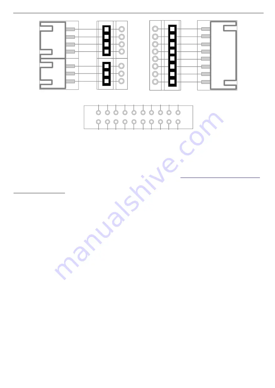
Figure 3. Demo Board connector's and contacts pinout.
5
Getting started
Download integrated development environment CannyLab at
www.cannylogic.com/downloads
.
Before you start working with the development kit, study the CannyLab user guide at
www.cannylogic.com.
Unpack the CANNY 7 Demo Kit.
Connect the CANNY 7 Demo Board with the controller installed using the miniUSB interface
cable included in the CANNY 7 Demo Kit, connecting the CANNY 7 Demo Board USB-A port (5) to
the miniUSB port of the CANNY 7 controller.
Turn the Keys Polarity Switch (13) and USB Mode Switch (12) of the CANNY 7 Demo Board to
the «OFF» position.
Connect the assembled CANNY 7 Demo Kit to PC / Laptop using the second included miniUSB
interface cable by connecting the demo board miniUSB connector (6) to the USB-A connector of the
personal computer.
Assembled CANNY 7 Demo Kit is shown on fig.4.
6
Working with CANNY 7 Demo Kit
The normal order of using CANNY 7 Demo Kit is presented in flowchart at fig.5.
Push-buttons (keys) are used to imitate external input signals at the controller's channels by
user if needed. To control the common polarity of the push-buttons at the input channels of the
controller, Keys Polarity Switch (13) is provided.
Note: In some modes, the operation of the controller as part of the CANNY 7 Demo Kit may differ
from its operation in the autonomous mode due to the slight influence of the active elements of
the demo board on the input / output circuits of the controller.
3
Rev.08122017
EXT2
Channel 2
Channel 1
Channel 0
Channel 7
Channel 6
Channel 5
Channel 4
Channel 3
X2
WX2
EXT1
X1
WX1
X3
WX3
Channel 8
Channel 9
Channel10
CAN-L
CAN-H
GND
+12
В
EXT3
C
ha
n. 0
C
ha
n.
1
C
ha
n. 2
C
ha
n.
3
C
ha
n.
4
C
ha
n.
5
C
ha
n. 6
C
ha
n.
7
+5
V
G
N
D
+1
2V
C
AN
-L
C
AN
-H
Х
4.
1
Х
4.
4
Х
4.
2
C
ha
n.
8
Х
4.
3
C
ha
n.
1
0
C
ha
n.
9
EXT4


