


PC300 / PC311E(P) l User’s Manual
30
Chapter 2: Switches and Connectors
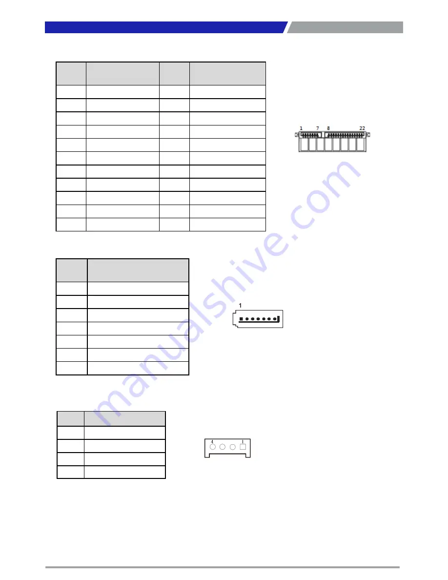
SATA1: SATA with Power Connector
Pin
Definition
Pin
Definition
1
GND
12
GND
2
SATA_TXP0
13
GND
3
SATA_TXN0
14
+5V
4
GND
15
+5V
5
SATA_RXN0
16
+5V
6
SATA_RXP0
17
GND
7
GND
18
GND
8
+3.3V
19
GND
9
+3.3V
20
+12V
10
+3.3V
21
+12V
11
GND
22
+12V
SATA2: SATA Connector
Pin
Definition
1
GND
2
SATA_TXP0
3
SATA_TXN0
4
GND
5
SATA_RXN0
6
SATA_RXP0
7
GND
POWER1, POWER2, POWER3: Power Connector
Connector Type: 1X4-pin Wafer, 2.0mm pitch
Pin
Definition
1
+5V
2
GND
3
GND
4
+12V
Summary of Contents for PC311E
Page 1: ...PC300 Series PC Module...
Page 8: ...Chapter 1 Product Introductions...
Page 17: ...PC300 PC311E P l User s Manual 17 1 4 2 PC311E PC311P Unit mm Chapter 1 Product Introductions...
Page 18: ...Chapter 2 Switches and Connectors...
Page 28: ...PC300 PC311E P l User s Manual 28 Chapter 2 Switches and Connectors...
Page 32: ...Chapter 3 System Setup...
Page 47: ...Chapter 4 BIOS Setup...
Page 73: ...Copyright 2016 C T Solution Inc All Rights Reserved www candtsolution com...


