C&K systems SYS3316RF Installation Instructions Manual Download Page 7

7

SYS3316RF Installation Manual

The last two Command Locations are CL 37 and CL A0. Pressing the [#]
key at these locations will advance you to CL 38 or CL A1, respectively.
Locations CL 38 and CL A1 are not used in the SYS3316RF. If you
accidentally enter either of these locations, press [*] [#] to exit program-
ming, or enter the Command Location number, followed by the [#] key, for
the location you wish to program.

To Exit Panel Programming

When you have finished programming, press [*] [#]. 

The panel will also

exit the programming mode if you do not press any key within a five
minute period.

PROGRAMMING the ALPHA KEYPAD

PROGRAMMING the ALPHA KEYPAD

PROGRAMMING the ALPHA KEYPAD

PROGRAMMING the ALPHA KEYPAD

PROGRAMMING the ALPHA KEYPAD

Ensure the Alpha keypad is wired to the SYS3316RF and power is applied
to the control panel. You can only access the programming mode when
the control panel is disarmed.

NOTE:

Programming the Keypad is not the same as Keypad
Programming.

The Alpha Keypad

You can program the Alpha keypads for special messages, each of the 16
zone labels, and the keypad address. Zone Labels display during the
walk-test and when the [#] key is pressed during alarm memory or faults.
The programmable Service Message is displayed during AC failure, fuse
failure, communication failure, or low battery. The Dealer Message
displays when the system is disarmed. The keypad address is initially
displayed only during system start up (see page 4, Keypad Addressing).

These messages can be programmed directly from the Alpha keypad or
remotely using the Commander II/Monitor II software package. For more
detailed information about remote programming, refer to the Commander
II/Monitor II Operating Manual.

Keypad Message Programming

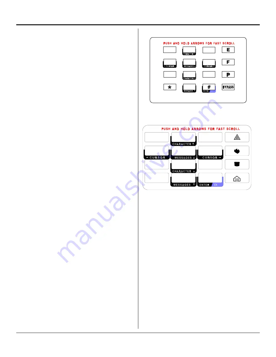
The Alpha keypad programming template is used to allow the installer
to program messages and zone descriptions into the Alpha keypads.
The template shown on the next page should be used when program-
ming the keypad.

To activate the keypad programming mode, enter the [Installer's Code]
[*] [0] [1] [#]. Information may be entered into the keypad in the form
of letters (upper and lower case), numbers (0 - 9), and 22 special symbols.
All characters are displayed in the order listed above, i.e. upper and
lower case letters, numbers, and special symbols. The [Space] char-
acter precedes the letter A.

To enter a Message or Label, use the [2] key to scroll through the
characters until you reach the desired character. If you scroll past the
desired character, the [8] key may be used to scroll backwards. When
the desired character is displayed, press the [6] key to move the cursor
to the next character position. The [4] key moves the cursor to the left.
When all characters have been entered, press the [#] key to write the
message and move to the next message position. Use the [0] key to
move backward through the messages.

The message order is:

• SERVICE MESSAGE

• DEALER MESSAGE

• SOFT ZONE IDENTIFIERS (A, B, and C)

• HARDWIRED LOOP IDENTIFIERS

• KEYPAD ADDRESS

Both the Alpha (shown at the top of the next column) and the Alpha Plus
(shown below in the next column) use the same procedure to program
messages.

ALPHA PLUS Programming Template

ALPHA PLUS Programming Template

ALPHA PLUS Programming Template

ALPHA PLUS Programming Template

ALPHA PLUS Programming Template

1

1

1

1

1

2

2

2

2

2

3

3

3

3

3

6

6

6

6

6

5

5

5

5

5

4

4

4

4

4

7

7

7

7

7

8

8

8

8

8

9

9

9

9

9

0

0

0

0

0

NOTE:

If you do not press any key for 5 minutes, the
keypad will automatically exit the programming
mode.

To Exit Keypad Programming

When you have finished programming, press [*] [#]. 

The keypad will also

exit the programming mode if you do not press any key within a five
minute period.

1

1

1

1

1

2

2

2

2

2

3

3

3

3

3

4

4

4

4

4

5

5

5

5

5

6

6

6

6

6

7

7

7

7

7

8

8

8

8

8

9

9

9

9

9

0

0

0

0

0

ALPHA II Programming Template

ALPHA II Programming Template

ALPHA II Programming Template

ALPHA II Programming Template

ALPHA II Programming Template

Summary of Contents for SYS3316RF

Page 1: ...ED BY FUSE F2 3AG 0 75A P N 5 051 396 00 Rev A P N 5 051 396 00 Rev A P N 5 051 396 00 Rev A P N 5 051 396 00 Rev A P N 5 051 396 00 Rev A All outputs are power limited Connect ground wire from door h...

Page 2: ...3 House hold Burglar Alarm System Units and UL 1635 Digital Burglar Alarm Communicator System Units The following programming restrictions must be observed to meet UL standards UL COMPLIANCE UL COMPLI...

Page 3: ...rmer to the wall DO NOT share the secondary of the transformer with other devices A foreign ground can damage the power supply voiding the warranty DO NOT use any transformer other than that specified...

Page 4: ...p seized 9 X PCF The 9 X PCF has eight flying leads on the other end Wire them to the phone line terminals as follows If you replace the battery after a SYSTEM TROUBLE LOW BATTERY message you must tes...

Page 5: ...terior SUPERVISED EOL circuit Zone 15 interior SUPERVISED EOL circuit Zone 16 interior SUPERVISED EOL circuit Emergency soft zone chirp audible non reporting Fire soft zone pulsed audible non reportin...

Page 6: ...ations A0 B3 and B4 with an LED keypad remember to enter the Command Location followed by the program data then press the key Warning If you enter a Command Location and then press the key without ent...

Page 7: ...to the Alpha keypads The template shown on the next page should be used when program ming the keypad To activate the keypad programming mode enter the Installer s Code 0 1 Information may be entered i...

Page 8: ...4 61 User 25 62 User 26 63 User 27 64 User 28 65 User 29 66 User 30 67 User 31 68 User 32 0 Arm Only with Closing Report Shunting Allowed 1 Disarm Only with Opening Report Shunting Allowed 2 Arm and D...

Page 9: ...ions Formats Command Location 0A Communications Formats Command Location 0A Communications Formats Command Location 0A Communications Formats 1 2 3 4 1 2 1 2 DefaultValues DefaultValues DefaultValues...

Page 10: ...n Digit Position 6 Dialing Attempts 1 1 try 2 2 tries 3 3 tries 4 4 tries 5 5 tries 6 6 tries 7 7 tries 8 8 tries 9 9 tries 0 10 tries 1 11 tries 2 12 tries 3 13 tries 4 14 tries 5 15 tries 1 2 3 4 5...

Page 11: ...mmand Location 0F Receiver 1 Phone Number digits 13 18 Command Location 0F Receiver 1 Phone Number digits 13 18 Command Location 0F Receiver 1 Phone Number digits 13 18 Command Location 0F Receiver 1...

Page 12: ...Receiver 2 Phone Number digits 7 12 Command Location 12 Receiver 2 Phone Number digits 7 12 Command Location 13 Receiver 2 Phone Number digits 13 18 Command Location 13 Receiver 2 Phone Number digits...

Page 13: ...igit Position 1 Alarm Receiver Select Digit Position 1 Alarm Receiver Select 0 Receiver 1 with Receiver 2 as back up 1 Receiver 1 only 2 Receiver 2 only 3 Receiver 1 and Receiver 2 Dual Reporting 0 5...

Page 14: ...3 Fire Receiver Select Digit Position 3 Fire Receiver Select Digit Position 3 Fire Receiver Select Digit Position 3 Fire Receiver Select Digit Position 4 Loop Bell Type Digit Position 4 Loop Bell Typ...

Page 15: ...porting Digit Position 5 Cancel Report Code Digit Position 5 Cancel Report Code Digit Position 5 Cancel Report Code Digit Position 5 Cancel Report Code Digit Position 5 Cancel Report Code Valid entrie...

Page 16: ...ress Report and Delays Digit Position 4 Exit Delay Time Digit Position 4 Exit Delay Time Digit Position 4 Exit Delay Time Digit Position 4 Exit Delay Time Digit Position 4 Exit Delay Time DefaultValue...

Page 17: ...mand Location 2F Unit Control Command Location 2F Unit Control Command Location 2F Unit Control DefaultValues DefaultValues DefaultValues DefaultValues DefaultValues 1 2 3 4 5 0 0 1 1 1 2 2 2 2 2 F F...

Page 18: ...rts Command Location 48 Trouble Reports Command Location 48 Trouble Reports Command Location 48 Trouble Reports Command Location 48 Trouble Reports 1 2 3 4 F 1 E 1 DefaultValues DefaultValues DefaultV...

Page 19: ...s Digit Position 2 Year 1 s Digit Position 2 Year 1 s Digit Position 2 Year 1 s Digit Position 2 Year 1 s Digit Position 2 Year 1 s Digit Position 3 Month 10 s Digit Position 3 Month 10 s Digit Posit...

Page 20: ...label into the slot on the back of the keypad base Once the installation is complete connect AC and DC power Complete programming if required Test all panel operations DS1 DS1 DS1 DS1 DS1 WATCH WATCH...

Page 21: ...Instant Home Arming Also called Instant Home Arming Also called Instant Home Arming Also called Instant Home Arming Also called Instant Home Arming Instant Arm Arms system and converts delayed zones...

Page 22: ...found at various locations throughout the programming section of the manual Question Question Question Question Question What is an Interface error 1 and how do I correct the error Answer Answer Answe...

Page 23: ...o communicate at the same time The only way to correct the problem is to disconnect one of the keypads and then re address the remaining one ensuring that the new address is not in use by any other ke...

Page 24: ...This option determines the response time of the loop itself It acts 49 50 2 Time as a buffer on the loop to minimize the possibility of fast acting sensors such as swingers or window foil producing f...

Page 25: ...the audible tone Unit Control 2F 3 Enable 4 minute Suppresses all trouble and alarm reports for a period of four Power Up minutes after power is initially applied to the panel This allows Delay the se...

Page 26: ...ot functioning properly when an intrusion or fire occurs is inadequate maintenace Your alarm system should be tested weekly to make sure all sensors are operating properly The SYS3316RF panel and keyp...

Page 27: ...er 15 User 15 User 15 User 15 Name Name Name Name Name 5 6 9 E 0 0 0 0 User 14 User 14 User 14 User 14 User 14 Name Name Name Name Name 5 5 9 E 0 0 0 0 User 13 User 13 User 13 User 13 User 13 Name Nam...

Page 28: ...ations Communications Communications Communications Formats Formats Formats Formats Formats 0 3 1 1 0 0 B 0 C 0 0 0 0 0 0 Account 1 Account 1 Account 1 Account 1 Account 1 Phone 1 1st 6 digits Phone 1...

Page 29: ...Control Control Control 1 9 0 3 E 3 0 0 Loop 3 Loop 3 Loop 3 Loop 3 Loop 3 Codes Codes Codes Codes Codes 1 8 0 2 E 2 0 0 Loop 2 Loop 2 Loop 2 Loop 2 Loop 2 Codes Codes Codes Codes Codes 1 A 0 4 E 4 0...

Page 30: ...p 1 Loop 1 Loop 1 Switches Switches Switches Switches Switches 0 1 0 0 3 2 Loop 3 Loop 3 Loop 3 Loop 3 Loop 3 Switches Switches Switches Switches Switches 0 1 0 0 3 4 Loop 5 Loop 5 Loop 5 Loop 5 Loop...

Reviews: