background image


RS02250/0717/CD 

www.cdtechno.com 


Part 3 - Safety Precautions


This battery is designed for industrial, stationary use only and is not intended for application in vehicular, 
starting, lighting and ignition (SLI), and the operation of portable tools and appliances.  
Use in accordance with this manual or all IEEE battery procedures. Use of this product other than in 
accordance with these instructions may produce hazardous and unsafe operating conditions, leading to 
damage of equipment and/or personal injury. 

Do not expose the batteries to open flame or electrical arc. Do not tamper with the vent, as this will  
void the warranty. 

Do  not  use  any  petroleum  based  cleaning  or  lubrication  solution  on  the battery  jar  or  cover.  Failure  to 
follow this warning may result in damage to the container and will void the warranty. 

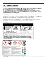
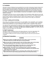
As a notice to all technicians and personnel in the near proximity of the batteries, a BCI and OSHA 
warning label is in plain view to indicate the potential hazards of battery systems. 


Figure 1 - BCI warning label 


Figure 2 

– OSHA warning label


Summary of Contents for Liberty AES

Page 1: ...RS02250 0717 CD 1 www cdtechno com Installation and Operating Manual RS02250 Revision Date 7 10 16 ...

Page 2: ... responsibility of the customer to provide adequate ventilation so hydrogen gas accumulation in the battery area does not exceed two percent by volume However normal air circulation in a ventilated facility will preclude any hydrogen build up even during equalize charging Never install batteries in a sealed cabinet or enclosure If you have any questions contact your local C D representative This b...

Page 3: ...Supplies 8 Part 4 Receiving 9 4 1 Inspection at Time of Delivery 9 4 2 Damage and Shortage Situations 9 Part 5 Storage 10 5 1 Storage Conditions 10 5 2 Storage Temperature and Duration 10 Part 6 Installation 10 6 1 Locating Battery System 10 6 2 Ventilation 12 6 3 Floor Loading and Anchoring 12 6 4 Spill Containment 12 6 5 Electrical Connections 12 6 6 Terminal Plates 13 6 7 Numbering Cells 13 6 8...

Page 4: ...Monthly Inspection 21 9 2 Quarterly 21 9 3 Semi Annually 21 9 4 Annually 21 9 5 Performance Tests 22 Part 10 Battery Degradation 22 10 1 General Information and Precautions 22 10 2 Float versus Cycle Life 22 10 3 Low Float Voltage and Sulfation 23 10 4 Hydration 23 10 5 Open Circuit Late Installations 214 10 6 Parallel Battery Strings 24 10 7 High Temperature Operation 24 Appendix 25 Appendix A In...

Page 5: ...ing applications or for float applications that include regular cycles Typical applications include Off Grid Unreliable grid Telecom Renewable energy or other stationary applications requiring a high number of cycles throughout the life of the cell For PSoC applications please consult C D for a recommended charge regime If your application is a Telecom Switchgear Control and UPS applications which...

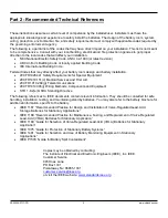
Page 6: ...rvices and First Aid 29CFR1 910 268 g Telecommunications 29CFR1910 305 j Wiring Methods Components and Equipment STD 1 8 2 e OSHA Standing Directive The following references to IEEE documents contain relevant information They should be consulted for safe handling installation testing and maintaining standby batteries You may also refer to the battery brochure for additional information specific to...

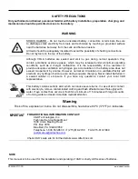
Page 7: ...fe operating conditions leading to damage of equipment and or personal injury Do not expose the batteries to open flame or electrical arc Do not tamper with the vent as this will void the warranty Do not use any petroleum based cleaning or lubrication solution on the battery jar or cover Failure to follow this warning may result in damage to the container and will void the warranty As a notice to ...

Page 8: ...odules or modules into position Fork lift or portable crane Insulated steel toed safety shoes remove all metals i e rings etc to ensure no short circuits Bicarbonate of soda 1 lb per gallon of water to neutralize and clean up any electrolyte Metric insulated tools to ensure no short circuits between connections Insulated torque wrench to ensure no short circuits between connections Digital voltmet...

Page 9: ...firm that the accessory package is present and the quantities are correct If help is required call C D customer service department to report any discrepancies 4 2 Damage and Shortage Situations C D ships FOB McAllen TX zip code 78503 title ownership passes to the ship to end user at the McAllen TX warehouse If shipments are damaged or if cartons or skids are damaged or missing a claim must be file...

Page 10: ...e battery and can cause potentially hazardous leakage Higher than normal storage temperature 77 F 25 C nominal will accelerate internal self discharge of a cell by a factor of two for each 15 F 10 C over nominal 77 F 25 C storage temperature This in turn will reduce the allowable time before initial and or boost charging If a freshening charge is required it is very important that boost or freshen...

Page 11: ...ecommended 2 4 00 between systems side to side where no side termination is being used is recommended Reference supplied C D system drawing for additional details 3 6 00 between systems side to side where side termination is being used is recommended 4 4 00 spacing from any wall equipment to the side of any system is recommended 5 When installing systems back to back 4 00 spacing is recommended fr...

Page 12: ...reference which is supplied with every shipment The Liberty 2V floor mounting base has provisions for floor anchoring Consult the applicable building codes and regulations for specific requirements In all cases floor anchoring is considered mandatory with floor anchors to be installed in all locations provided unless otherwise specified Floor anchor sizing and hardware are the responsibility of th...

Page 13: ...l of the battery and follow the electrical circuit with succeeding numbers on the cell covers 6 8 Interconnection Cell series connection is made from the of one cell to the of the next sequential cell It is essential that the cell location and orientation match the included drawing All connections must be made as indicated on the drawing with no deviations If no drawing is provided or it is lost c...

Page 14: ... or corroded connections When checking connections disconnect the battery from the load and the charging equipment and follow all the precautionary measures outlined above and in the general safety references Some resistance measurement equipment may cause a spark when the probes are applied to the cell posts Use appropriate safety precautions when conducting this measurement Typical cell and conn...

Page 15: ... charger The recommended method of providing an initial freshening charge section 5 2 and section 7 1 7 2 is to first determine the maximum allowable voltage that may be applied by the connected equipment Divide this by the number of cells in the battery to obtain maximum average voltage per cell allowed by the equipment Adjust this number to a recommended value found in Table 1 and continue charg...

Page 16: ...age multiplied by the number of cells in the battery string Individual cell float voltages may vary by 0 10 0 05 volts from the average in a single string b Average string float voltage must be adjusted based on temperatures which are above or below 77 F 25 C see section 8 4 c Charging time will vary due to temperature if cell temperature is below 60 F 16 C double the charge time for initial or eq...

Page 17: ...ian If you observe any unusual readings or visual indications consult your C D Technologies Representative and send a copy of your latest maintenance report to your local C D Representative or the technical services department at C D Cell ohmic readings may vary by 20 of the C D Technologies published values This variation does not necessarily indicate a problem with the condition of the battery I...

Page 18: ...e system cannot achieve a full charge between discharging cycles or if the system is being utilized in a PSoC operation then additional charging needs to be employed to bring it back to full charge at least once month The charging system should be capable of automatically adjusting the charging voltage based on the temperature of the battery The measurement of the battery temperature must be taken...

Page 19: ...pending on how the system is designed the batteries are regularly discharged and regularly re charged In these applications the charging system should be sized so that on the average the battery is returned to between 85 to 90 state of charge daily On a bi weekly to monthly basis the battery should be charged to 100 or fully charged state using the equalization parameters outline in Table 1 Sectio...

Page 20: ... the float voltage must be adjusted by 2mV per F or 3 6mV per C Adjust as indicated below Add 2mV 0 002 volts per F or 3 6mV per C below 77 F 25 C Subtract 2mV 0 002 volts per F or 3 6mV per C above 77 F 25 C If the battery is operated at temperatures below the recommended range the capacity will be reduced even with temperature compensated charging which must be accounted for during initial syste...

Page 21: ...er than 50 require further attention such as a load test 5 Measure and record the temperature of the negative terminal on each cell 9 3 Semi Annually including the above 6 Measure and record the individual cell voltages 9 4 Annually including the above 7 Torque cell bolts to 110in lbs 12 4 N m Any disassembled connections should be re torqued to 110 in lb 12 4 N m 8 Measure and record connector re...

Page 22: ... interfacing electronics such as an uninterruptible power supply UPS system The name stationary implies the battery is usually permanently placed in a given location and not transferred from place to place in its service life As such standby battery life is directly affected by and will be degraded if subjected to repeated cycling Depth of discharge number of discharges rate of discharge and the i...

Page 23: ... to the observer the plates will become sulfated If you suspect sulfated plates contact the C D Technical Services Department 1 800 543 8630 or 1 215 619 2700 for assistance Sulfated batteries are not fully charged batteries thus have not completed the electrochemical reaction of recharge Accordingly they will have reduced capability If allowed to remain in a partially charged condition for an ext...

Page 24: ...lleling valve regulated batteries is necessary the external circuit resistance should be matched for each battery A wide variation in battery circuit resistance can result in unbalanced discharge i e excessive discharge currents in some batteries and less discharge in others As a consequence cell failures in one battery string and the subsequent loss of performance capacities of that string will r...

Page 25: ...ve honeycomb hood cardboard packaging and shrink wrap See Figure A1 Carefully remove all shipping materials and dispose of properly Once all shipping materials are removed unbolt the system from the shipping pallet Each system will be provided with one base assembly See Figure A2 for floor anchoring and should be removed first followed by any other bolted connection leaving only the module rivets ...

Page 26: ...ce base assembly into position and mark the anchor locations using the base as a template See Figure A5 A6 2 Four 13 16 20 6mm holes are provided in the system base for floor anchoring 3 Install floor anchors and reposition base onto anchors See Figure A6 4 Install anchor hardware and verify top surface of base assembly is level in both axes if necessary install shims to level base 5 Once base ass...

Page 27: ...ur while lifting however once released and in position will return to square See Figure A8 2 Battery Lift Table Again prior to hoisting install only the 4 10mm bolts in the rear flanges Verify module orientation then position module on lift table keeping metal surfaces isolated from battery terminals The modules flat top and bottom surfaces allow it to easily slide from the lift platform to the ba...

Page 28: ...sure proper cell orientation Doing so can save time and effort in the future if a module is installed in the incorrect orientation 2 Once the module is in position and bolt holes are in alignment make the Module to Module connection using 4 10mm bolts 2 side in the horizontal plane Torque to 40 ft lb 55 N m See Figure A13 3 Follow these steps for any additional modules for tiers 2 on up Note Modul...

Page 29: ...h the C D layout drawing attach the restraint bar using 4 10mm bolt assemblies See Figure A14 Top Restraint Each system stack will be supplied with one top restraint The top restraint will be installed on the upper most module to complete the assembly The restraint will be installed using 6 10mm bolt assemblies See Figure A15 Final Check Once the top restraint is attached the system assembly is co...

Page 30: ...ting base 4 Be sure the floor mounting base or assembly is in position and level and then torque the floor anchors If the base is not level use shims to level A level base is particularly important for the stability and safety of these high narrow stacks See Figure A7 5 If the assembly requires additional modules use the lifting slings Place additional modules one at a time on top of modules alrea...

Page 31: ...mixed with one gallon of water wipe the cover and terminal seal area with a cloth moistened with the neutralizing solution Do not allow the neutralizing solution to enter the cell Rinse with clear water and dry thoroughly 3 Lightly brush the terminal cable lug or terminal plate contact surfaces with a plastic brush or medium grade Scotch Brite removing any oxidized or corroded areas Note Liberty 2...

Page 32: ... 32 www cdtechno com Appendix C SDS Documentation For the most up to date SDS information please visit the C D Technologies public website Public Website www cdtechno com SDS Sheets http cdtechno com resource sds html ...

Page 33: ... cells and 3 75 for four post cells This tool shown in Figure D2 is available from your local C D Technologies Representative or directly through C D Customer Service customersvc cdtechno com 8 Prepare for cell removal by moving a platform lift or equivalent lifting apparatus in proximity to the bottom of the stack module from which the cell is to be removed Make sure all exposed metal on the plat...

Page 34: ...der C D Ship Date Positive Posts Date Installed Battery Model Negative Posts Cells X Strings Application Cell Covers Bus Voltage Portable Meter Bus Voltage Equipment Final Presence of Lubricant on cells Yes No Charger Size Charger Type Charger Serial Charger Mfg Ambient Room Temperature Last Discharge Peak Load Current Amp Or KW Typical Load Current KW Cell Arrangement Appearance of Following Batt...

Page 35: ...STATUS Open Circuit Float Equalize BATTERY BUS VOLTAGE Vdc Vdc Vdc LOCATION Cell Volts 2 000 Serial Connection Resistance Internal Cell Conductance Impedance Resistance Cell Volts 2 000 Serial Connection Resistance Internal Cell Conductance Impedance Resistance ...

Page 36: ...s are recyclable and C D Technologies currently has a low cost convenient and environmentally safe collection and recycling program Visit the C D Web site at www cdtechno com for further information on our Revert Pb battery recycling program or call 1 866 RevertPb 866 738 3787 ...

Page 37: ...RS02250 0717 CD 37 www cdtechno com ...

Page 38: ...RS02250 0717 CD 38 www cdtechno com ...

Page 39: ...ies express or implied with regard to the accuracy or completeness of such information Further because the product s featured herein may be used under conditions beyond its control C D Technologies Inc hereby disclaims all warranties either express or implied concerning the fitness or suitability of such product s for any particular use or in any specific application or arising from any course of ...

Reviews: