background image

pg. 10

INSTALLATION

7. INSTALLING THE LIGHT KIT

Light kit plate

Mounting ring

Screw

Screw

Light kit plate

Light kit

Halogen bulb

White wire

Black wire

Light kit plate

Glass shade

ATTENTION: The Energy Policy Act of 2005 requires this fan to be equipped 

with a 190 watt limiting device, If lamping exceeds 190watts, the ceiling fan’s 

light kit will shut off automatically.

Remove one of three screws from the fan motor assembly mounting ring, and 
loosen the other two screws, but do not remove. 
Place the key holes from the light kit plate over the two screws previously 
loosened from the fan motor assembly mounting ring. Turn the light kit plate 
until it locks in place at the narrow section of the key holes. Secure by tightening 
the two screws previously loosened and the one screw previously removed. 
Remove one of three screws from the light kit plate, and loosen the other two 
screws, but do not remove. 
Connect the white wire from the fan motor assembly to the white wire from 
the light kit.
Connect the black wire from the fan motor assembly to the black wire from 
the light kit.
Place the key holes from the light kit over the two screws previously loosened 
from the light kit
plate. Turn the light kit until it locks in place at the narrow section of the key 
holes. Secure by tightening the two screws previously loosened and the one 
screw previously removed.
Install the halogen bulb into the socket located in the light kit.
Attach the glass shade to the light kit plate by twisting tightly.

Summary of Contents for CITIE

Page 1: ...RS QUESTIONS OR CONCERNS CONTACT CANARM AT 1 800 265 1833 ENGLISH 1 800 567 2513 FRENCH Monday through Friday 8 00 a m to 5 00 p m EST IMPORTANT FOR YOUR RECORDS RECORD AND KEEP THE FOLLOWING INFORMAT...

Page 2: ...RIALS REQUIRED Adjustable wrench Phillips screwdriver Blade screw driver Step ladder Wire cutters Wiring supplies as required to reduce the risk of personal injury DO NOT bend the blade brackets when...

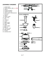
Page 3: ...screws 6 wood screws at washers 7 downrod 8 canopy 9 canopy cover 10 yoke cover 11 bolt 12 cotter pin 13 motor 14 blade screw 15 ber washer 16 blade 17 light kit plate 18 light kit 19 75W E11 bulb 20...

Page 4: ...canopy and downrod insert bolt through hole in shaft and downrod be careful not to damage or cut the fan wires secure bolt with cotter pin secure downrod in position by tightening jam screws and lock...

Page 5: ...nd at washers supplied through outer slots of mounting bracket and into the wood joist Leave one of the wood screws suf ciently loose to allow the safety cable to be looped around before nal tightenin...

Page 6: ...e tab of the mounting bracket place looped end of safety cable over the wood screw and at washer not previously tightened in Step 3 tighten above wood screw securing the safety cable 3 HOOKING UP SAFE...

Page 7: ...echeck to make sure the switches on the remote control and the receiver are set to the same position Any combination of settings will operate the fan as long as the remote control and receiver are set...

Page 8: ...res are on the other side Carefully tuck the wire connections up into the outlet box your ceiling fan to meet your speci c requirements Should the following method not meet your requirements call or v...

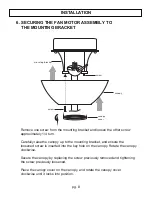
Page 9: ...rew approximately 1 4 turn Carefully raise the canopy up to the mounting bracket and ensure the loosened screw is inserted into the key hole on the canopy Rotate the canopy clockwise Secure the canopy...

Page 10: ...sembly Blade screw Fiber washer Blade Insert the blades through the slots on the fan motor assembly Attach the fan blades to the fan motor assembly using the blade screws and fiber washer and tighten...

Page 11: ...l it locks in place at the narrow section of the key holes Secure by tightening the two screws previously loosened and the one screw previously removed Remove one of three screws from the light kit pl...

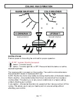
Page 12: ...up NOTE Wait for the fan to stop before reversing the direction of the blade rotation Warm weather Counterclockwise Direction A downward air flow creates a cooling effect This allows you to set your a...

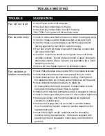
Page 13: ...in period to eliminate noises Fan wobbles or shakes excessively check that all blades are screwed rmly into blade brackets check that all blade brackets are secured rmly to motor check distance from...

Page 14: ......

Page 15: ......

Page 16: ...with proof of purchase For the balance of the warranty four 4 years the MOTOR WINDINGS ONLY shall be free of defects We will correct such defects or replace the motor assembly at our option if the pr...

Reviews: