EN-Rev IM-FDM-EU/1.7 Copyright © April 2019. Canadian Solar Inc.
14 |
ANNEX B:
FRAMELESS DYMOND MODULE
INSTALLATION MANUAL SUPPLEMENT
All the basic requirements of the main
installation manual should apply to this
supplement, unless otherwise specified.
The loads described in this manual correspond
to test loads. For installations complying with
IEC 61215-2:2016 and UL 1703, a safety factor
of 1.5 should be applied for calculating the
equivalent maximum authorized design loads.
Project design loads depend on construction,
applicable standards, location and local
climate. Determination of the design loads
is the responsibility of the racking suppliers
and / or professional engineers. For detailed
information, please follow local structural code
or contact your professional structural engineer.
Corner protector is not included in below
illustrations.
A
A
A
A
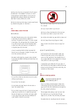
Clamping on module long side, four clamp points;
Mounting rails must run perpendicularly to the
module long side.
Clamping Location Illustration
Illustration A
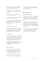
Clamping on module long side, six clamp points;
Mounting rails must run perpendicularly to the
module long side.
Illustration B
A
A
A
A
B
B
B
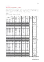
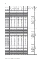
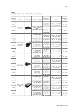
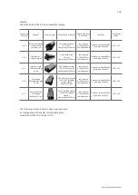
The following clamps in table 2 have been approved
as compatible with Canadian Solar double glass
module CS6K-P-FG, CS6K-M-FG and CS6K-MS-FG.
B


