6
This appliance uses two transformers to supply a low DC
voltage circuit for energizing the control as well as a low AC
voltage to energize the actuator. The voltage on the
secondary side of the DC transformer should be 24 VDC
when measured with a voltmeter. The voltage on the
secondary side of the AC transformer should be 24 VAC. A
3.3A circuit breaker is provided on the secondary side of the
AC transformer. A tripped circuit breaker indicates a short
in the 24VAC energizing the actuator and must be
corrected.
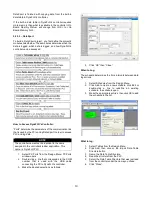
The 24VDC transformer that energizes the control is
located inside the control box on the bottom left. The 24VAC
transformer which energizes the actuator is located inside
the control box on the bottom right. They can be seen in the
image below:
4.2
– Field Power Supply
The main field 120VAC power supply can be inserted
through the knock-out holes that are placed on the sides of
the control box mounted on top of the heat exchanger
cabinet. This connection must be made by a licensed
electrician, when the unit is not energized, and in
accordance with section 4.1 of this manual. A strain relief
should be used. The connections should be made to the
terminals that are shown in the image below (the product
will have actual labels on the electrical mounting plate):
4.3
– Fuses
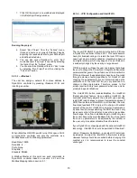
The DynaFLO is equipped with two fuses. One is to protect
the pump and the other fuse is to protect the controller.
These two fuses are shown in the image below. The fuse
holder on the top contains a glass cylinder 1Amp fuse that
protects the controller. The fuse holder on the bottom
contains a bigger glass cylinder fuse that is rated for 2Amps
which protects the pump.


