48
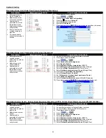
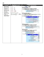
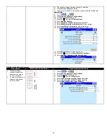
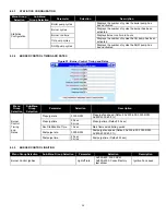
Isolation Valve Operation (ALL Boilers)
Description
Electrical Connection(s)
Programming Instructions
Building pump varies flow through
boiler based on demand
Sequence of operation where two or
more boilers or programmed to
operate in lead lag
1.
Lead isolation valve is opened
using Pump B (Central Heat
Pump) contacts
2.
Remote Operator closes to
initiate call for heat
3.
Prepurge, Honeywell SOLA
checks that all boiler safeties
are closed before ignition
attempt
4.
Lead boiler fires up to base load
rate (Default: 80%) for a period
of time (Add Stage: Interstage
delay)
5.
An additional boiler is needed
when:
Lead lag temp < (Lead lag
setpoint
– Add stage Error
threshold) AND (Interstage
delay timer has expired)
6.
Lag boiler is called to start
7.
15-second delay exists between
a call for heat and closure of
Pump B contacts
8.
Lag boiler performs prepurge,
Honeywell SOLA checks that all
boiler safeties are closed before
ignition attempt
9.
Lead boiler fires up to base load
rate and both boilers modulate
in unison up to 100% or as low
as 4% based on heating
demand
10. Lag boiler shuts down first
when:
Lead lag temp > (Lead lag
se Drop stage Error
threshold)
11. Lag boiler isolation valve
remains open for overrun time
(Default: 1 minute)
12. All boilers off:
Lead lag temp > (Lead lag
se off hysteresis)
13. Lead boiler isolation valve
remains open for overrun time
(Default: 1 minute). Lag boiler
isolation valve also opens for
overrun time to remove any
residual heat that may have
accumulated inside boiler.
14. Lag boiler electronic isolation
valve is closed, and lead boiler
electronic isolation valve
remains open
1)
Press
and
2)
Select
Pump Configuration
3)
Scroll to
Central Heat Pump
4)
Select
Pump start delay
. Change this to 15 seconds
a.
If the Pump start delay parameter does not appear on
screen, use the following steps:
b.
Go to the Home Screen
c.
Press
d.
Press
e.
Press
f.
Enter Register Address:
292
g.
Press
h.
Enter Register Value:
15
i.
Press
5)
Select
6)
Uncheck CH: Demand*
7)
Uncheck CH: Service Active*
8)
Uncheck Local Lead Lag: Service Active*
9)
Aux pump: X is set
Summary of Contents for ADVANTUS AVH 500
Page 2: ......
Page 3: ......
Page 38: ...31 Figure 23 Recommended Piping with Reverse Return and Variable Primary Flow...
Page 88: ...81 PART 12 EXPLODED VIEW Figure A...
Page 89: ...82 Figure B FAN BURNER ASSEMBLY AV500 600 some items may not be as shown...
Page 90: ...83 Figure C FAN BURNER ASSEMBLY AV800 4000 some items may not be as shown...
Page 91: ...84 Figure D Figure E...
Page 92: ...85 Figure F Figure G...
Page 93: ...86 Figure H CONTROL BOARD ASSEMBLY...
Page 100: ...93 PART 13 ELECTRICAL DIAGRAMS...
Page 101: ...94...
Page 102: ...95...


