29
4.10
LOW WATER CUTOFF (If Equipped)
If this boiler is installed above radiation level, a low water cut-off device must be installed at the time of boiler installation. Some local
codes require the installation of a low water cut-off on all systems. Electronic low water cut-offs are available as a factory supplied option
on all models. Low water cut-offs should be tested every six months, including flushing of float types. The normally open switch contact
of the low water cutoff is to be wired in series with the flow switch. A
Hold
condition message will be indicated on the control display on a
low flow condition.
Caution
Remove jumper when connecting to 24 VAC circuit.
4.11
RELIEF VALVE
This appliance is supplied with a relief valve sized in accordance with ASME Boiler and Pressure
Vessel Code, Section IV (“Heating
Boilers”). The relief valve is to be installed in the vertical position and mounted in the hot water outlet. No valve is to be placed between
the relief valve, and the appliance. To prevent water damage, the discharge from the relief valve shall be piped to a suitable floor drain
for disposal when relief occurs. No reducing couplings or other restrictions shall be installed in the discharge line. The discharge line shall
allow complete drainage of the valve and line. Relief valves should be manually operated at least once a year. If a relief valve discharges
periodically, this may be due to thermal expansion in a closed water supply system. Contact the water supplier or local plumbing inspector
on how to correct this situation. Do not plug the relief valve.
CAUTION
Avoid contact with hot discharge water
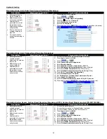
Connection detail for placing
L.W.C.O in 24V circuit
WARNING: Be sure to remove the
jumper between H and P1
Figure 20: Low Water Cut Off Electrical Connections (Watts)
Figure 21: Low Water Cut Off Electrical Connections (ITT)
Summary of Contents for ADVANTUS AVH 500
Page 2: ......
Page 3: ......
Page 38: ...31 Figure 23 Recommended Piping with Reverse Return and Variable Primary Flow...
Page 88: ...81 PART 12 EXPLODED VIEW Figure A...
Page 89: ...82 Figure B FAN BURNER ASSEMBLY AV500 600 some items may not be as shown...
Page 90: ...83 Figure C FAN BURNER ASSEMBLY AV800 4000 some items may not be as shown...
Page 91: ...84 Figure D Figure E...
Page 92: ...85 Figure F Figure G...
Page 93: ...86 Figure H CONTROL BOARD ASSEMBLY...
Page 100: ...93 PART 13 ELECTRICAL DIAGRAMS...
Page 101: ...94...
Page 102: ...95...


