background image

NL115 Table of Contents 

PDF viewers:  These page numbers refer to the printed version of this document.  Use the 
PDF reader bookmarks tab for links to specific sections. 

1.  Introduction

..................................................................1 

2.  Cautionary  Statements

...............................................1 

3.  Initial Inspection

..........................................................1 

4  Quickstart

......................................................................1 

4.1  Physical Set-up .........................................................................................2 
4.2  Communicating via Ethernet ....................................................................2 

4.2.1  Step 1 – Configure Datalogger .......................................................2 
4.2.2  Step 2 – LoggerNet Set-up..............................................................3 
4.2.3  Step 3 – Connect .............................................................................4 

4.3  Programming the Datalogger to Send Data to the NL115 ........................4 
4.4  CF Card Data Retrieval ............................................................................5 

5  Overview

........................................................................6 

5.1  Status LEDs ..............................................................................................6 
5.2  Power ........................................................................................................6 
5.3  CF Card Data Retention............................................................................6 

6  Specifications

...............................................................7 

7.  Operation

......................................................................8 

7.1  TCP/IP Functionality ................................................................................8 

7.1.1  Communicating over TCP/IP..........................................................8 

7.1.1.1  Data Call-back.......................................................................8 
7.1.1.2  Datalogger-to-Datalogger Communication ...........................9 

7.1.2  HTTP Web Server ........................................................................10 
7.1.3  FTP................................................................................................11 

7.1.3.1  FTP Server ..........................................................................11 
7.1.3.2  FTP Client ...........................................................................13 

7.1.4  Telnet ............................................................................................14 
7.1.5  Ping ...............................................................................................14 
7.1.6  Serial Server..................................................................................14 

7.1.6.1  Serial Input ..........................................................................14 
7.1.6.2  Serial Output .......................................................................15 

7.1.7  TCP ModBus ................................................................................15 
7.1.8  DHCP............................................................................................15 
7.1.9  DNS ..............................................................................................15 

Summary of Contents for NL115

Page 1: ...NL115 Ethernet and CompactFlash Module Revision 6 12 C o p y r i g h t 2 0 0 6 2 0 1 2 C a m p b e l l S c i e n t i f i c I n c...

Page 2: ......

Page 3: ...emoving reinstalling and shipping defective products to Campbell Campbell will return such products by surface carrier prepaid within the continental United States of America To all other locations Ca...

Page 4: ...g container Campbell Scientific s shipping address is CAMPBELL SCIENTIFIC INC RMA _____ 815 West 1800 North Logan Utah 84321 1784 For all returns the customer must fill out a Statement of Product Clea...

Page 5: ...tep 3 Connect 4 4 3 Programming the Datalogger to Send Data to the NL115 4 4 4 CF Card Data Retrieval 5 5 Overview 6 5 1 Status LEDs 6 5 2 Power 6 5 3 CF Card Data Retention 6 6 Specifications 7 7 Ope...

Page 6: ...Data Collection Constraints 23 7 4 2 Transporting CF Card to Computer 24 7 4 2 1 Converting File Formats 24 7 4 2 2 Reinserting the Card 25 7 4 2 3 Card Swapping 25 Appendices A Formatting CF Card A 1...

Page 7: ...kly begin using an NL115 for straightforward Ethernet communications and data storage operations The remainder of the manual is a technical reference which describes in detail such operations as TCP I...

Page 8: ...to the datalogger Insert formatted CF card For instructions on formatting a CF card see Appendix A A CF card does not need to be present in order to use the NL115 s TCP IP functionality NOTE FIGURE 4...

Page 9: ...splayed NOTE 4 2 2 Step 2 LoggerNet Set up The next step is to run LoggerNet and configure it to connect to the datalogger via the Ethernet port a In LoggerNet s Setup Screen press Add Root and choose...

Page 10: ...table data display and data collection are now possible 4 3 Programming the Datalogger to Send Data to the NL115 The CardOut instruction is used in the datalogger program to send data to the CF card T...

Page 11: ...arameter is 1 so all available space on the card will be allocated to the table DataTable Table1 1 1 CardOut 0 1 Minimum 1 batt_volt FP2 0 False Sample 1 PTemp IEEE4 EndTable To prevent losing data co...

Page 12: ...rol and eject The LED indicates the status of the module The LED will flash red when the CF card is being accessed solid green when it is OK to remove the card solid orange to indicate an error and fl...

Page 13: ...Meets requirements for a class A device under European Standards Application of Council Directive s 89 336 EEC as amended by 89 336 EEC and 93 68 EEC Standards to which conformity is declared EN55022...

Page 14: ...CP IP This includes program send and data collection These are straightforward operations and are accomplished through LoggerNet s Connect screen For more information see the LoggerNet manual Data cal...

Page 15: ...31 6785 0 SendVariables Result1 Socket 1 4094 0000 100 Public Callback dummy1 1 CallTable CLBK1 NextScan EndProg 7 1 1 2 Datalogger to Datalogger Communication Communications between dataloggers is po...

Page 16: ...Public PTemp PTemp_Base 1 CallTable Test NextScan EndProg 7 1 2 HTTP Web Server Typing the datalogger s IP address into a web browser will bring up its home page as shown in Figure 7 1 This default ho...

Page 17: ...quires first writing the file to the datalogger s USR drive It is less convenient and the page will be only as current as it is written to the file NOTE 7 1 3 FTP 7 1 3 1 FTP Server With an NL115 atta...

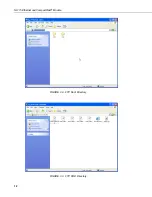
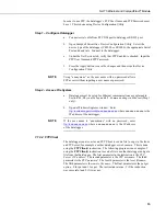
Page 18: ...NL115 Ethernet and CompactFlash Module FIGURE 7 2 FTP Root Directory FIGURE 7 3 FTP CRD Directory 12...

Page 19: ...hysical Set up and 4 2 Communicating via Ethernet Step 1 only b Open a Windows Explorer window Enter ftp username password nnn nnn nnn nnn where nnn nnn nnn nnn is the IP address of the datalogger If...

Page 20: ...an Ethernet 7 1 6 1 Serial Input The TCPOpen instruction must be used first to open up a TCP socket An example of this instruction is shown below The first parameter in TCPOpen is the IP address to o...

Page 21: ...Editor Help result SerialOut socket sent 0 100 7 1 7 TCP ModBus With an NL115 attached the datalogger can be set up as a TCP ModBus Master or Slave device For information on configuring the datalogger...

Page 22: ...n additional records if no lapses occurred If more lapses occur than were anticipated there may be fewer records in the file than were allocated The CardConvert software included in LoggerNet PC400 an...

Page 23: ...card or delete the powerup ini file after the powerup ini upload 7 2 3 1 Creating and Editing Powerup ini Powerup ini is created with a text editor then saved as powerup ini Some text editors such as...

Page 24: ...r1 CPU 7 2 3 2 Applications Commands 1 2 6 13 and 14 Run Now and or Run On Power up If a device other than CRD drive is specified the file will be copied to that device Command 1 2 13 Run On Power up...

Page 25: ...p ini Files Example 7 2 through Example 7 7 are example powerup ini files EXAMPLE 7 2 Run Program on Power up Copy pwrup cr1 to USR will run only when powered up later 2 pwrup cr1 usr EXAMPLE 7 3 Form...

Page 26: ...he number of data sets records for which to allocate memory in the CF card Each time a variable or interval trigger occurs a line or row of data is output with the number of values determined by the O...

Page 27: ...rds which will be written before the table is full and data storage stops Once 1000 records have been stored data storage will stop PROGRAM CR1000 Public temp DataTable Table1 1 1000 CardOut 1 1000 Sa...

Page 28: ...rameter is negative so all available memory on the card will be allocated to these tables once space for the fixed size tables has been allocated The datalogger will attempt to size the tables so that...

Page 29: ...program to ensure data are not written to the CF card while data are retrieved Otherwise data corruption and confusion will result 7 4 1 1 Fast Storage Data Collection Constraints When LoggerNet coll...

Page 30: ...ata files can be copied to another drive or used directly from the CF card just as one would from any other disk In most cases however it will be necessary to convert the file format before using the...

Page 31: ...datalogger If a CF card was not properly accepted the NL115 will flash orange In that case the user needs to reformat and erase all data contained on the CF card Formatting or erasing a CF card might...

Page 32: ...e all data files from the card Windows98 and WindowsME users need to shift delete to completely delete files Using standard delete may create an invisible recycle bin on the CF card NOTE 6 At the next...

Page 33: ...xplorer 2 the CR1000KD or 3 LoggerNet File Control A 1 Windows Explorer To format card using Windows Explorer 1 Insert CF card into CF adapter or CF reader 2 Windows Explorer should identify a drive a...

Page 34: ...ither FAT or FAT 32 A 2 CR1000KD To format card using the CR1000KD 1 Insert CF card into NL115 2 From Main Menu of CR1000KD choose PCCard 3 Choose Format Card 4 Choose Yes to proceed A 3 LoggerNet Fil...

Page 35: ...Appendix A Formatting CF Card 3 Choose FileControl under the Tools menu of the Connect screen 4 Highlight CRD 5 Press Format 6 Press Yes to confirm A 3...

Page 36: ...Appendix A Formatting CF Card A 4...

Page 37: ...the following characteristics high density low cost bit sequential access scalable and a single standard There are two types of NAND Flash memory Single Level Cell SLC and Multi Level Cell MLC SLC NAN...

Page 38: ...s with a datalogger TABLE B 3 Comparison of Industrial and Commercial Grade Cards Industrial Grade Cards Commercial Grade Cards Operating Temperature 40 to 85 C 0 to 70 C Vibration Proofing 30 Gs 15 G...

Page 39: ...C NAND Flash for Cost Effective High Capacity Memory written by Raz Dan and Rochelle Singer September 2003 Rev 1 1 www data io com pdf NAND MSystems Implementing_MLC_NAND_Flash pdf 2 Advantages of SLC...

Page 40: ...Appendix B PC CF Card Information B 4...

Page 41: ......

Page 42: ...ntific Canada Corp CSC 11564 149th Street NW Edmonton Alberta T5M 1W7 CANADA www campbellsci ca dataloggers campbellsci ca Campbell Scientific Centro Caribe S A CSCC 300 N Cementerio Edificio Breller...

Reviews: