background image

Precautions 

DANGER 

 MANY HAZARDS ARE ASSOCIATED WITH INSTALLING, USING, MAINTAINING, AND WORKING ON OR AROUND 

TRIPODS, TOWERS, AND ANY ATTACHMENTS TO TRIPODS AND TOWERS SUCH AS SENSORS, CROSSARMS, ENCLOSURES, 
ANTENNAS, ETC

.  FAILURE TO PROPERLY AND COMPLETELY ASSEMBLE, INSTALL, OPERATE, USE, AND MAINTAIN TRIPODS, 

TOWERS, AND ATTACHMENTS, AND FAILURE TO HEED WARNINGS, INCREASES THE RISK OF DEATH, ACCIDENT, SERIOUS 
INJURY, PROPERTY DAMAGE, AND PRODUCT FAILURE.  TAKE ALL REASONABLE PRECAUTIONS TO AVOID THESE HAZARDS.  
CHECK WITH YOUR ORGANIZATION'S SAFETY COORDINATOR (OR POLICY) FOR PROCEDURES AND REQUIRED PROTECTIVE 
EQUIPMENT PRIOR TO PERFORMING ANY WORK. 

Use tripods, towers, and attachments to tripods and towers only for purposes for which they are designed.  Do not exceed design 
limits.  Be familiar and comply with all instructions provided in product manuals.  Manuals are available at www.campbellsci.com or 
by telephoning (435) 227-9000 (USA).  You are responsible for conformance with governing codes and regulations, including safety 
regulations, and the integrity and location of structures or land to which towers, tripods, and any attachments are attached.  Installation 
sites should be evaluated and approved by a qualified engineer.  If questions or concerns arise regarding installation, use, or 
maintenance of tripods, towers, attachments, or electrical connections, consult with a licensed and qualified engineer or electrician. 

General 


Prior to performing site or installation work, obtain required approvals and permits. Comply 
with all governing structure-height regulations, such as those of the FAA in the USA. 


Use only qualified personnel for installation, use, and maintenance of tripods and towers, and 
any attachments to tripods and towers.  The use of licensed and qualified contractors is highly 
recommended. 


Read all applicable instructions carefully and understand procedures thoroughly before 
beginning work. 


Wear a

 hardhat 

and

 eye protection

, and take 

other appropriate safety precautions

 while 

working on or around tripods and towers.


Do not climb

 tripods or towers at any time, and prohibit climbing by other persons. Take 

reasonable precautions to secure tripod and tower sites from trespassers. 


Use only manufacturer recommended parts, materials, and tools. 

Utility and Electrical 


You can be killed

 or sustain serious bodily injury if the tripod, tower, or attachments you are 

installing, constructing, using, or maintaining, or a tool, stake, or anchor, come in 

contact with


overhead or underground utility lines


Maintain a distance of at least one-and-one-half times structure height, 20 feet, or the distance 
required by applicable law, 

whichever is greater

, between overhead utility lines and the 

structure (tripod, tower, attachments, or tools). 


Prior to performing site or installation work, inform all utility companies and have all 
underground utilities marked. 


Comply with all electrical codes.  Electrical equipment and related grounding devices should 
be installed by a licensed and qualified electrician. 

Elevated Work and Weather 


Exercise extreme caution when performing elevated work. 


Use appropriate equipment and safety practices. 


During installation and maintenance, keep tower and tripod sites clear of un-trained or non-
essential personnel.  Take precautions to prevent elevated tools and objects from dropping. 


Do not perform any work in inclement weather, including wind, rain, snow, lightning, etc. 

Maintenance 


Periodically (at least yearly) check for wear and damage, including corrosion, stress cracks, 
frayed cables, loose cable clamps, cable tightness, etc. and take necessary corrective actions. 


Periodically (at least yearly) check electrical ground connections. 

WHILE EVERY ATTEMPT IS MADE TO EMBODY THE HIGHEST DEGREE OF SAFETY IN ALL CAMPBELL SCIENTIFIC PRODUCTS, 
THE CUSTOMER ASSUMES ALL RISK FROM ANY INJURY RESULTING FROM IMPROPER INSTALLATION, USE, OR 
MAINTENANCE OF TRIPODS, TOWERS, OR ATTACHMENTS TO TRIPODS AND TOWERS SUCH AS SENSORS, CROSSARMS, 
ENCLOSURES, ANTENNAS, ETC. 


Summary of Contents for LI200X

Page 1: ...INSTRUCTION MANUAL LI200X Pyranometer Revision 1 15 C o p y r i g h t 1 9 9 4 2 0 1 5 C a m p b e l l S c i e n t i f i c I n c ...

Page 2: ......

Page 3: ...ducts to CSI CSI will return such Products by surface carrier prepaid within the continental United States of America To all other locations CSI will return such Products best way CIP port of entry per Incoterms 2010 This warranty shall not apply to any Products which have been subjected to modification misuse neglect improper service accidents of nature or shipping damage This warranty is in lieu...

Page 4: ...ng container Campbell Scientific s shipping address is CAMPBELL SCIENTIFIC INC RMA _____ 815 West 1800 North Logan Utah 84321 1784 For all returns the customer must fill out a Statement of Product Cleanliness and Decontamination form and comply with the requirements specified in it The form is available from our web site at www campbellsci com repair A completed form must be either emailed to repa...

Page 5: ...fore beginning work Wear a hardhat and eye protection and take other appropriate safety precautions while working on or around tripods and towers Do not climb tripods or towers at any time and prohibit climbing by other persons Take reasonable precautions to secure tripod and tower sites from trespassers Use only manufacturer recommended parts materials and tools Utility and Electrical You can be ...

Page 6: ......

Page 7: ...ting 6 7 2 Mounting to an Instrument Mount 6 7 2 1 Required Tools 6 7 2 2 Mounting Procedure 6 7 2 2 1 CM225 Solar Sensor Mounting Stand 6 7 2 2 2 015ARM 8 7 3 Wiring 10 7 4 Programming 10 7 4 1 Total Solar Radiation 11 8 Maintenance 11 9 Calibration 12 10 Troubleshooting 12 Appendices A Importing Short Cut Code A 1 A 1 Importing Short Cut Code into a Program Editor A 1 B Example Program B 1 B 1 E...

Page 8: ...LI200X Schematic 10 C 1 Unmodified Pyranometer Wiring Schematic C 1 Tables 7 1 Connections to Campbell Scientific Dataloggers 10 7 2 Multipliers Required for Average Flux and Total Flux Density in Sl and English Units 11 B 1 Wiring for Example Program B 1 C 1 Multipliers Required for Average Flux and Total Flux Density for SI and English Units for a LI200S Pyranometer C 2 ii ...

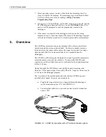
Page 9: ...lthough the LI200X is rugged it should be handled as a precision scientific instrument The black outer jacket of the cable is Santoprene rubber This compound was chosen for its resistance to temperature extremes moisture and UV degradation However this jacket will support combustion in air It is rated as slow burning when tested according to U L 94 H B and will pass FMVSS302 Local fire codes may p...

Page 10: ...n should place a shortcut icon on the desktop of your computer To open Short Cut click on this icon 3 When Short Cut opens select New Program 4 Select Datalogger Model and Scan Interval default of 5 seconds is OK for most applications Click Next 2 ...

Page 11: ...w The flux density defaults to kW m 2 and the total flux defaults to MJ m 2 This can be changed by clicking the Flux Density or Total Flux box and selecting one of the other options 6 After selecting the sensor click at the left of the screen on Wiring Diagram to see how the sensor is to be wired to the datalogger The wiring diagram can be printed out now or after more sensors are added 3 ...

Page 12: ...ad The detector outputs current a shunt resistor in the sensor cable converts the signal from current to voltage allowing the LI200X to be measured directly by Campbell Scientific dataloggers The LI200X is calibrated against an Eppley Precision Spectral Pyranometer to accurately measure sun plus sky radiation Do not use the LI200X under vegetation or artificial lights because it is calibrated for ...

Page 13: ... CR1000 CR3000 CR5000 and CR9000 X Stability 2 change over a 1 year period Response Time 10 µs Cosine Correction Cosine corrected up to 80 Operating Temperature 40 to 65 C Temperature Dependence 0 15 per C Relative Humidity 0 to 100 Detector High stability silicon photovoltaic detector blue enhanced Sensor Housing Weatherproof anodized aluminum case with acrylic diffuser and stainless steel hardwa...

Page 14: ...e Mounting height is not critical for the accuracy of the measurement However pyranometers mounted at heights of 3 m or less are easier to level and clean 7 2 Mounting to an Instrument Mount 7 2 1 Required Tools Tools required for installation on a tripod or tower Small and medium Phillips screwdrivers 1 2 in open end wrench for CM225 or 015ARM Tape measure UV resistant cable ties Side cut pliers ...

Page 15: ...t nuts 3 Place the LI200X in the center of the LI2003S base leveling fixture 4 Loosely mount the LI2003S base leveling fixture on the CM225 Do not fully tighten the three mounting screws CM225 Stand CM200 Series Crossarm U bolt Nuts Bubble Level Holes for Mounting Screws LI2003S Base Leveling Screws Holes for Mounting Screws 7 ...

Page 16: ...ly leveled and adjust as necessary 7 Route the sensor cable along the underside of the crossarm to the tripod tower and to the instrument enclosure 8 Secure the cable to the crossarm and mast using cable ties 9 Remove the red cap after installing the sensor Save this cap for shipping or storing the sensor 7 2 2 2 015ARM 1 Secure the 015ARM to the mast by tightening the U bolt nuts Leveling Screws ...

Page 17: ...he assembly in its final position Check that the pyranometer is still correctly leveled and adjust as necessary 6 Route the sensor cable along the underside of the 015ARM s arm to the tripod tower and to the instrument enclosure 7 Secure the cable to the mounting arm and mast using cable ties 8 Remove the red cap after installing the sensor Save this cap for shipping or storing the sensor Bubble L...

Page 18: ...ear Shield 40 2 to 90 2 Ω RED BLACK WHITE CLEAR H L AG OR GND GND FIGURE 7 1 LI200X Schematic 7 4 Programming Short Cut is the best source for up to date datalogger programming code Programming code is needed when creating a program for a new datalogger installation when adding sensors to an existing datalogger program If your data acquisition requirements are simple you can probably create and ma...

Page 19: ...integration option as shown in the example program Solar radiation can be reported as an average flux density W m 2 or daily total flux density MJ m 2 The appropriate multipliers are listed in TABLE 7 2 Programming examples are given for both average and daily total solar radiation Negative values should be set to zero before being processed TABLE 7 2 Multipliers Required for Average Flux and Tota...

Page 20: ...ut voltage by the calibrated current output For example a pyranometer with a calibration of 92 µA kW 1 m2 will have the resistor set to 54 35 Ω 5 0 092 1 2 1 2 mV kW m mA kW m 10 Troubleshooting Symptom 9999 or radiation values around 0 1 Check that the sensor is wired to the Differential channel specified by the measurement instruction 2 Verify that the Range code is correct for the datalogger ty...

Page 21: ...d exit Short Cut Make note of the file name used when saving the Short Cut program 2 Open CRBasic Editor 3 Click File Open Assuming the default paths were used when Short Cut was installed navigate to C CampbellSci SCWin folder The file of interest has a CR6 CR1 CR8 CR3 or CR5 extension for CR6 CR1000 CR800 CR3000 or CR5000 dataloggers respectively Select the file and click Open 4 Immediately save...

Page 22: ...Appendix A Importing Short Cut Code mark begins each line This character instructs the datalogger compiler to ignore the line when compiling the datalogger code A 2 ...

Page 23: ...le a daily total flux density is found This total flux density is in MJ m 2 day 1 Negative values are set to zero before they are added to the running total CR1000 Declare Variables and Units Public SlrW Public SlrMJ Units SlrW W m Units SlrMJ MJ m Define Data Tables DataTable Table1 True 1 DataInterval 0 60 Min 10 Average 1 SlrW FP2 False EndTable DataTable Table2 True 1 DataInterval 0 1440 Min 1...

Page 24: ...Appendix B Example Program convert mV to W m2 SlrW SlrW 200 0 Call Data Tables and Store Data CallTable Table1 CallTable Table2 NextScan EndProg B 2 ...

Page 25: ...nstruction 2 see Section 7 4 Programming C 2 Unmodified Pyranometers Pyranometers that do not have variable or fixed shunt resistors built into the cable can still be measured by Campbell Scientific dataloggers This is done by wiring in a 100 Ω shunt resistor directly onto the datalogger wiring panel The input range and multipliers vary from one pyranometer to another See Appendix C 3 Input Range ...

Page 26: ... s surface is 1 kW m 2 Thus an estimate of the maximum input voltage is obtained by multiplying the calibration by the maximum expected irradiance In this example that product is 8 7 mV Now select the smallest input range which is greater than the maximum expected input voltage In this case the 25 mV slow range for the CR10 and 15 mV slow range for the 21X are selected C 4 Multiplier The multiplie...

Page 27: ......

Page 28: ...om br Campbell Scientific Canada Corp CSC 14532 131 Avenue NW Edmonton AB T5L 4X4 CANADA www campbellsci ca dataloggers campbellsci ca Campbell Scientific Centro Caribe S A CSCC 300 N Cementerio Edificio Breller Santo Domingo Heredia 40305 COSTA RICA www campbellsci cc info campbellsci cc Campbell Scientific Ltd CSL Campbell Park 80 Hathern Road Shepshed Loughborough LE12 9GX UNITED KINGDOM www ca...

Reviews: