background image

IRGASON® Integrated CO

2

/H

2

O Open-Path Gas Analyzer and 3D Sonic Anemometer

69

Summary of Contents for IRGASON

Page 1: ...Revision 08 2021 Copyright 2010 2021 Campbell Scientific Inc Product Manual ...

Page 2: ...ng 12 6 3 Wiring and connections 15 7 Settings 19 7 1 Factory defaults 20 7 2 Bandwidth 20 7 3 SDM address 21 7 4 Unprompted output 21 7 5 Unprompted output rate 21 7 6 RS 485 baud rate 21 7 7 Analog output 21 7 8 ECMon update rate 21 7 9 Temperature sensor 22 7 10 Fixed temperature value 22 7 11 Pressure sensor 22 7 11 1 Pressure gain 22 7 11 2 Pressure offset 22 7 11 3 Fixed pressure value 23 7 ...

Page 3: ...0 1 Data collection and processing with EasyFlux DL 43 10 2 Data logger programming with CRBasic 45 10 2 1 EC100 instruction 46 10 3 EC100Configure instruction 49 10 3 1 ConfigCmd 11 zero and span control 51 10 3 2 ConfigCmd 18 heater voltage 52 10 4 Example CRBasic program 53 11 Theory of operation 54 11 1 IRGASON sonic anemometer 54 11 1 1 Wind speed 54 11 1 2 Temperature 55 11 2 IRGASON gas ana...

Page 4: ...Appendix C Equations 64 Appendix D Safety data sheets SDS 67 D 1 Molecular sieve Type 13X 68 D 2 Magnesium perchlorate 72 D 3 Decarbite 79 Appendix E IRGASON packing information 83 Table of Contents iii ...

Page 5: ...dizing agents sodium hydroxide caustic soda NaOH and anhydrous magnesium perchlorate Mg ClO4 2 If you are handling or exchanging the scrubber bottles see Replacing desiccant and scrubber bottles p 40 use the following precautions IRGASON instrument shipped after July 2017 contain a 13X molecular sieve instead n Avoid direct contact with the chemicals n Ensure your work area is well ventilated and ...

Page 6: ... option could make troubleshooting difficult and may lead to the user not being aware of potential problems with the instrumentation see EC100 outputs p 27 o Resting the analyzer on its side during the zero and span procedure may result in measurement inaccuracy o When cleaning the gas analyzer window make sure the alcohol and any residual water completely evaporate before proceeding with the zero...

Page 7: ...m temperature it has no spatial displacement between the sample volumes of the gas analyzer and the sonic anemometer and the EC100 synchronously samples data from the gas analyzer and sonic anemometer 5 Specifications 5 1 Measurements Features l To compute carbon dioxide and water vapor fluxes using the eddy covariance method the IRGASON measures o absolute carbon dioxide o water vapor densities o...

Page 8: ...ating temperature 30 to 50 C Gas analyzer Measurement precision2 CO2 density 0 2 mgCO2 m 3 0 15 µmolCO2 mol 1 H2O density 0 00350 gH2O m 3 0 006 mmolH2O mol 1 Factory calibrated range CO2 0 to 1000 µmolCO2 mol 1 H2O 0 mmolH2O mol 1 to 37 C dewpoint Analyzer temp 30 to 50 C Baro pressure 70 to 106 kPa CO2 performance Zero max drift3 0 55 mgCO2 m 3 C 1 0 3 μmolCO2 mol C 1 Gain Drift 0 1 of reading µ...

Page 9: ...curacy5 Offset error ux uy 8 cm s 1 uz 4 cm s 1 Gain error Wind vector 5 horizontal 2 of reading Wind vector 10 horizontal 3 of reading Wind vector 20 horizontal 6 of reading Sonic reporting range Full scale wind 65 553 m s Sonic temperature 50 to 60 C Auxiliary sensors6 Barometer Basic barometer Accuracy 30 to 0 C 3 7 kPa at 30 C falling linearly to 1 5 kPa at 0 C 0 to 50 C 1 5 kPa Measurement ra...

Page 10: ... selectable 2 noise rms assumes l 25 C l 85 kPa l 14 g m 3 H2O l 597 mg m 3 CO2 l 20 Hz bandwidth 3 30 to 50 C 4 noise rms 5 assumes l 30 to 50 C l wind speed 30 m s 1 l azimuth angles between 170 6 refer to manufacturer s product brochure or manual for details 5 2 Output signals Features l EC100 electronics outputs data using o CS SDM o RS 4857 IRGASON Integrated CO2 H2O Open Path Gas Analyzer an...

Page 11: ...olution 76 µV 16 bit Update rate 60 Hz Accuracy at 25 C 3 mV CO2 density equation mg m 3 0 38632 mVout 102 59 Full scale range 103 to 1829 mg m 3 H2O density equation g m 3 0 00865 mVout 2 26 Full scale range 2 to 41 g m 3 7 user selectable 8 Synchronous Device for Measurement A Campbell Scientific Inc proprietary serial interface for data logger to peripheral and sensor communication See SDM outp...

Page 12: ... Dimensions IRGASON Length 51 5 cm 20 3 in Height 31 1 cm 12 2 in Cable Length 3 m 9 8 ft EC100 Enclosure 24 1 x 35 6 x 14 cm 9 5 x 14 0 x 5 5 in Weight IRGASON with cable 2 8 kg 6 1 lbs EC100 with enclosure 3 2 kg 7 1 lbs Designed EC100 ingress protection rating IP65 Designed IRGASON ingress protection rating IP67 IRGASON Integrated CO2 H2O Open Path Gas Analyzer and 3D Sonic Anemometer 8 ...

Page 13: ...FIGURE 5 1 IRGASON dimensions side view IRGASON Integrated CO2 H2O Open Path Gas Analyzer and 3D Sonic Anemometer 9 ...

Page 14: ...FIGURE 5 2 IRGASON dimensions front view IRGASON Integrated CO2 H2O Open Path Gas Analyzer and 3D Sonic Anemometer 10 ...

Page 15: ...e sulfur containing compounds in viticulture attempt to mount the IRGASON in a way that reduces the exposure of the sonic transducers to saltwater or corrosive chemicals In marine or viticulture environments the sonic transducers are expected to age more quickly and require replacement sooner than a unit deployed in an inland chemical free environment NOTE The ingress protection rating of the EC10...

Page 16: ... sensor body See Data collection and processing with EasyFlux DL p 43 for additional information about the wind information reported by the sonic coordinate system 5 Mount the IRGASON assembly by fitting the boom adapter over the end of the crossarm Tighten the set screws on the boom adapter with a 3 16 inch hex socket head wrench WARNING Handle the IRGASON carefully The optical source may be dama...

Page 17: ...e nuts Finally attach the EC100 enclosure to the bracket by loosening the bolts on the back of the enclosure hanging the enclosure on the mounting bracket it should slide into place and be able to securely hang from the bracket and tightening the bolts see FIGURE 6 3 p 14 FIGURE 6 1 Exploded view of mounting the IRGASON WARNING Overtightening bolts will damage or deform the mounting hardware IRGAS...

Page 18: ...0 enclosure mounting bracket mounted on a vertical mast left and a tripod leg right FIGURE 6 3 Exploded view of mounting the EC100 enclosure IRGASON Integrated CO2 H2O Open Path Gas Analyzer and 3D Sonic Anemometer 14 ...

Page 19: ...mpbellsci com 9 Remove the EC100 enclosure desiccant from the plastic bag and place it in the mesh pocket of the enclosure Attach the humidity indicator card to the inside of the enclosure FIGURE 6 4 Mounting the IRGASON temperature probe 6 3 Wiring and connections FIGURE 6 5 p 16 FIGURE 6 6 p 17 FIGURE 6 7 p 17 show the EC100 electronics panel the bottom of the EC100 enclosure and sensor connecti...

Page 20: ...3 Connect the IRGASON sonic cable Similar to a begin by removing the black rubber cable entry plug found on the bottom left of the EC100 enclosure Insert the cable entry plug on the cable into the slot and connect the male end to the female connector labeled Sonic Anemometer on the EC100 electronics see FIGURE 6 5 p 16 The sonic cable is approximately 3 m 9 8 ft in length FIGURE 6 5 EC100 electron...

Page 21: ...formation is stored in the gas and sonic connectors of the IRGASON rather than in the EC100 This means that any IRGASON may be used with any EC100 FIGURE 6 7 Sensor connections to EC100 IRGASON Integrated CO2 H2O Open Path Gas Analyzer and 3D Sonic Anemometer 17 ...

Page 22: ...disconnect the gas analyzer or sonic connectors while the EC100 is powered 6 Connect a communications signal cable to the EC100 Loosen the nut on one of the cable entry seals Cable 1 or Cable 2 on the base of the EC100 enclosure remove the plastic plug plug may be stored in mesh pocket of enclosure insert the cable and retighten the nut by hand Refer to the sections below on SDM USB RS 485 and Ana...

Page 23: ...r or to another 12 VDC source 9 Once power is applied to the EC100 three status LEDs on the EC100 panel will illuminate The power LED is green and the sonic and gas LEDs are orange until the unit has warmed up and is ready to make measurements at which time the LEDs become green If after several minutes the LEDs turn red a diagnostic flag has been detected Check the individual diagnostic bits to d...

Page 24: ...ctuations in CO2 and H2O or else the high frequency contributions to the flux will be lost The factory default bandwidth of the EC100 is 20 Hz which is sufficient for most flux applications Lower bandwidth settings may be used for higher measurement heights which inherently have lower frequency content Refer to Filter bandwidth and time delay p 58 for more information on the digital filter options...

Page 25: ...is setting determines the output rate for unprompted output USB or RS 485 see USB or RS 485 output p 28 If the unprompted output is disabled this parameter is not used The factory default output rate is 10 Hz but it may be set to 10 20 or 60 Hz 7 6 RS 485 baud rate If the unprompted output mode is set to RS 485 this parameter determines the baud rate Otherwise this setting is not used The RS 485 b...

Page 26: ...ordered with the optional enhanced barometer model CS106 This setting defaults to EC100 Enhanced if the CS106 is ordered and to EC100 Basic otherwise There are two other possible settings for Pressure Sensor First the user may supply a different pressure sensor In this case the setting should be changed to User Supplied with the appropriate values for gain and offset entered see below The final op...

Page 27: ...ons An automatic heater control algorithm can be activated from either Device Configuration Utility or ECMon by putting in a value of 2 or deactivated by putting in a value of 1 NOTE Automatic heater control is available in EC100 OS version 4 07 or greater and is turned on by default starting with the OPEC program version 3 2 The algorithm uses the internal heaters to maintain a temperature that i...

Page 28: ... logger for control may be found at the end of EC100Configure instruction p 49 7 14 ECMon Settings for the IRGASON are easily verified or changed using the Windows PC support software ECMon Eddy Covariance Monitor which is found at www campbellsci com downloads Launch ECMon and connect the EC100 electronics to the PC with the included EC100 USB cable The USB connection for the EC100 electronics is...

Page 29: ...FIGURE 7 1 Main window of ECMon software IRGASON Integrated CO2 H2O Open Path Gas Analyzer and 3D Sonic Anemometer 25 ...

Page 30: ...n See ECMon p 24 for notes on installing a USB driver After launching Device Configuration Utility select EC100 from the list of device types The EC100 electronics should be connected to the PC with the EC100 USB cable and the appropriate USB port selected before connecting Once connected the settings tab displays all the current settings The Apply button must be clicked to save any changes Device...

Page 31: ...0 data logger On CR1000 data loggers the SDM protocol uses ports C1 C2 and C3 These are multipurpose control ports that are SDM activated when an SDM instruction is used in the data logger program On CR3000 and CR5000 data loggers the SDM protocol uses SDM dedicated ports SDM C1 SDM C2 and SDM C3 On CR6 data loggers the user must assign which set of three ports will be used for SDM This is done in...

Page 32: ...ettings p 19 The Unprompted Output setting must be set to USB or RS 485 If RS 485 is selected the RS485 Baud Rate must be set The Unprompted Output Rate must be set to the desired output rate All output data are formatted as comma delimited ASCII To view the data in terminal mode in Device Configuration Utility choose Unknown as the device type and enter Connect Each record terminates with a carri...

Page 33: ...et al 2016 NOTE An open path gas analyzer connected to an EC100 running an OS version less than 7 01 the 13th data field element is unused If a closed path gas analyzer for example an EC155 is connected to the EC100 this data field element will be the sample cell pressure differential FIGURE 8 1 An example of USB data output in terminal mode The final data element in each row or output array is th...

Page 34: ...0xaaaa and a pointer passed to the first byte of the output array The number of bytes in the output array should be entered in as the swath The returned value is the computed signature signature signature algorithm Standard signature is initialized with a seed of 0xaaaa Returns signature unsigned short signature unsigned char buf int swath unsigned short seed unsigned char msb lsb unsigned char b ...

Page 35: ...calibration 9 1 Routine maintenance Periodically do the following l Check the humidity indicator card in the EC100 enclosure If the highest dot has turned pink replace or recharge the desiccant bags Replacement desiccant may be purchased from Campbell Scientific or obtained elsewhere See the manual ENC10 12 ENC12 14 ENC14 16 ENC16 18 available at www campbellsci com for more details on recharging ...

Page 36: ...icks during the winter The wicks will accumulate snow or freezing rain resulting in blockage of the sonic signals The Spare Sonic Wicks Kit consists of three top wicks three bottom wicks and an installation tool see FIGURE 9 2 p 33 The installation tool is used by placing a wick over the angled end of the tool placing the straight end of the tool gently against the transducer face and sliding the ...

Page 37: ...or encroach on the optical path Before installation record signal strengths for both H2O and CO2 Following installation these values should be unchanged Wicks are available as listed in Table 9 1 p 33 Table 9 1 Rain wick replacement parts Wick Campbell Scientific Inc part number Campbell Scientific description Bottom wick 28652 IRGASON or EC150 Rain Wick Bottom Top wick 28653 IRGASON or EC150 Rain...

Page 38: ...sing a data logger see EC100Configure instruction p 49 for more details FIGURE 9 3 Proper location of the gas analyzer top wick left and bottom wick right 9 3 Gas analyzer window cleaning The windows of the analyzer should be cleaned if the signal strength for CO2 or H2O drops below 0 7 or 70 of the original value These values may be monitored in the output data or they can be viewed with ECMon To...

Page 39: ...conditions or in very remote sites performing a monthly zero will help mitigate the drift in the analyzer s measurements The first part of the following procedure simply measures the CO2 and H2O zero and span without making adjustments This allows the CO2 and H2O gain factors to be calculated These gain factors quantify the state of the analyzer before the zero and span procedure and in theory cou...

Page 40: ...nimize the length of the shroud Make sure the rubber seals on the ends of the shroud are clean and in good condition Position one end of the shroud over the lower snout and twist the top part of the shroud allowing it to extend and cover the upper snout while doing so avoid making contact with the sonic transducers Continue twisting the shroud until it is fully extended and covering both snouts Tw...

Page 41: ... appropriate USB port and click Connect The main screen should now be reporting real time CO2 and H2O concentrations Click Zero Span A graph will appear in the lower half of the zero and span window showing measured CO2 and H2O concentrations see FIGURE 9 5 p 38 8 Connect a gas tank of known CO2 concentration to a pressure regulator then to a flow controller and finally to the intake of the shroud...

Page 42: ...the reported CO2 concentration NOTE Use mixtures of CO2 and ambient air for the CO2 span gas The use of reference CO2 gas mixtures in pure nitrogen will lead to errors due to a carrier gas effect on pressure broadening of the CO2 absorption lines since oxygen gas has a smaller line broadening coefficient than nitrogen FIGURE 9 5 ECMon zero and span window IRGASON Integrated CO2 H2O Open Path Gas A...

Page 43: ...r is sufficient and the shroud is correctly seated on the snouts NOTE If using a Campbell Scientific Zero Air Generator instrument a pressure regulator and flow controller is not needed as the maximum achievable flow rate is 0 2 liters per minute 11 Examine the measurements that were written down for span CO2 span H2O and zero air Compute the drift in instrument gain using the following equation w...

Page 44: ...to stabilize 16 Enter the known dew point in C in the box labeled Span Dew Point and press Span 17 The zero and span procedure is now complete Remove the shroud reconnect the IRGASON temperature probe and prepare the site for normal operation 9 5 Replacing desiccant and scrubber bottles If more than two years have passed since replacing the desiccant scrubber bottles within the IRGASON or if the z...

Page 45: ...IGURE 9 6 Replacing the desiccant and CO2 scrubber bottles replacement bottles purchased after July 2017 may appear different than in the figure 9 6 Factory recalibration When the IRGASON is manufactured the gas analyzer is calibrated over a wide range of temperatures pressures and gas concentrations All CO2 calibration gases used in this process are mixtures of CO2 in ambient air and are traceabl...

Page 46: ...to an EC100 and powered on wind offsets may be viewed by connecting the EC100 to a PC and using ECMon to graph ux uy and uz wind components see ECMon p 24 In this zero wind environment ux and uy should be less than 8 cm s 1 0 08 m s 1 and uz should be less than 4 cm s 1 0 04 m s 1 If recalibration is deemed necessary contact Campbell Scientific 10 Data collection and data processing Data from the ...

Page 47: ...onic s orientation The compass coordinate system is fixed to Earth For the EasyFlux DL program to compute the correct compass wind direction the azimuth of the sonic negative x axis must be entered into the program The output value for the compass coordinate system is WD and the output value for the sonic coordinate system is WD_ Sonic The program default value for the variable sonic_azimuth is 0 ...

Page 48: ...he compass coordinate system the wind direction WD is 200 To calculate the wind direction in FIGURE 10 1 p 44 the orientation of the sonic anemometer relative to due north is needed in the program FIGURE 10 2 p 45 is in a right handed coordinate system and the wind vector direction is measured in degrees counterclockwise from the positive x axis Therefore the wind vector direction WD_ sonic is 70 ...

Page 49: ...the EC100Configure which receives and sends configuration settings With programs such as EasyFlux DL there is little need for the user to become well versed in the CRBasic language and the instructions required for communicating with the EC100 In those cases in which it is needed or desired the Campbell Scientific website has several tutorials and guidance for learning the CRBasic language They ca...

Page 50: ...e loaded into Dest 1 if a signature error on SDM data occurs EC100Cmd Dest variable length 0 8 1 12 2 13 SDMAddress defines the address of the IRGASON with which to communicate Valid SDM addresses are 0 through 14 Address 15 is reserved for the SDMTrigger instruction EC100Cmd is a parameter that requests data from the analyzer The results for the command are returned in the array specified by the ...

Page 51: ...surements compensates for spectroscopic effects during high sensible heat flux regimes as explained in Helbig et al 2016 NOTE An open path gas analyzer connected to an EC100 running an OS version less than 7 01 the 13th data field element is unused If a closed path gas analyzer for example an EC155 is connected to the EC100 this data field element will be the sample cell pressure differential As s...

Page 52: ...4 4 Sys Startup Gas analyzer is starting up 3 0x8 8 Motor Speed Motor speed outside of limits 4 0x10 16 TEC Temp TEC temperature exceeds limits 5 0x20 32 Light Power Source power exceeds limits 6 0x40 64 Light Temp Invalid source temperature 7 0x80 128 Light I Source current exceeds limits 8 0x100 256 Power Off Gas head not powered 9 0x200 512 Chan Err Gas input data out of sync with home pulse 10...

Page 53: ...nfigure to be placed in conditional statements Running from the processing task has ramifications when attempting to execute EC100Configure while other SDM instructions are executing in pipeline mode EC100Configure locks the SDM port during the duration of its execution If the pipelined SDM task sequencer needs to run while the SDM is locked it will be held off until the instruction completes This...

Page 54: ...er ConfigCmd is a variable that indicates whether to get or set a setting The options are listed in Table 10 4 p 50 DestSource is a variable that will contain the value to read when getting a setting or that will contain the value to send when writing a setting to the IRGASON Table 10 4 ConfigCmd Values for Setting and Retrieving Settings ConfigCmd variable Setting description some settings list p...

Page 55: ...Output Rate 10 10 Hz 20 20 Hz 99 motor spin rate 24 124 EC155 Pressure Sensor Type 0 Differential 1 Absolute 25 125 Sonic Transducer Shadow Correction 0 Disable 1 Enable 99 N A Save Settings to EEPROM memory 10 3 1 ConfigCmd 11 zero and span control To perform zeroing of CO2 and H2O ConfigCmd 11 is set to 1 After the IRGASON completes the zero it will write the value to 1 The data logger program c...

Page 56: ...s 6 ohms so the heater power PH expressed as Watts W is given by The maximum power at 4 0 V is 2 4 W Operating the heaters following a precipitation event encourages water droplets on the windows to evaporate more quickly thus restoring signal strength Heater usage may also be used to prevent formation of dew and frost on the windows which leads to invalid measurements due to differences in absorp...

Page 57: ...ias sonic_irga 10 cell_press Alias sonic_irga 11 CO2_sig_strgth Alias sonic_irga 12 H2O_sig_strgth Units Ux m s Units Uy m s Units Uz m s Units Ts C Units diag_sonic arb Units CO2 mg m 3 Units H2O g m 3 Units diag_irga arb Units cell_tmpr C Units cell_press kPa Units CO2_sig_strgth arb Units H2O_sig_strgth arb DataTable ts_data TRUE 1 DataInterval 0 0 mSec 10 Sample 12 Ux IEEE4 EndTable BeginProg ...

Page 58: ...the sonic anemometer pulses two ultrasonic signals in opposite directions The time of flight of the first signal out is given by Eq 1 and the time of flight of the second signal back is given by Eq 2 where to time of flight out along the transducer axis tb time of flight back in the opposite direction ua wind speed along the transducer axis d distance between the transducers and c speed of sound T...

Page 59: ... et al 2001 Eq 5 The speed of sound in moist air is a function of temperature and humidity and is given by Eq 6 where g ratio of specific heat of moist air at constant pressure to that at constant volume P pressure r air density Rd gas constant for dry air Tv virtual temperature T air temperature and q specific humidity defined as the ratio of the mass of water vapor to the total mass of air Kaima...

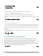
Page 60: ...is included in the sonic virtual temperature The sonic virtual temperature in degrees Celsius is given by Eq 10 p 56 where gd 1 4 and Rd 287 04 J K 1 kg 1 Eq 10 11 2 IRGASON gas analyzer The IRGASON gas analyzer is a non dispersive mid infrared absorption analyzer Infrared radiation is generated in the upper arm of the analyzer head before propagating along a 15 cm optical path Chemical species lo...

Page 61: ...g the intensity of nearby non absorbing wavelengths 4 µm for CO2 and 2 3 µm for H2O These measurements account for any source and detector aging and window contamination The chopper wheel spins at a rate of 60 revolutions per second and the detector is measured 512 times per revolution resulting in a detector sampling rate of 30 72 kHz The detector is maintained at 40 C using a three stage thermoe...

Page 62: ...quired to anti alias a desired signal bandwidth may result in large unwieldy data sets The covariance calculation itself relaxes the need for the ideal bandwidth First the time averaged typically 30 minute covariance calculations inherently reduce noise and second aliasing does not degrade the accuracy of covariance calculations Therefore the factory default for the EC100 bandwidth 20 Hz is rather...

Page 63: ...scan rate through SDM communications see EC100 outputs p 27 This process synchronizes EC100 gas and wind data with other signals measured by the data logger to within 8 33 ms plus or minus one half of the inverse of 60 Hz Alternatively when sending data to a non Campbell data acquisition system the EC100 down samples its USB and RS 485 outputs to a user selectable rate of 10 25 or 50 Hz Although t...

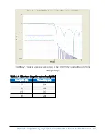
Page 64: ... of the EC100 10 Hz bandwidth and a 50 ms moving average Table A 1 Filter time delays for various bandwidths Bandwidth Hz Time delay ms 5 800 10 400 12 5 317 20 200 IRGASON Integrated CO2 H2O Open Path Gas Analyzer and 3D Sonic Anemometer 60 ...

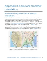
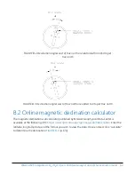
Page 65: ...ocal airport or through a NOAA web calculator Online magnetic declination calculator p 62 A general map showing magnetic declination for the Conterminous United States in 2015 is shown in FIGURE B 1 p 61 Declination angles east of true north are considered negative and are subtracted from 360 degrees to get true north as shown in FIGURE B 2 p 62 Declination angles west of true north are considered...

Page 66: ...on calculator The magnetic declination web calculator published by NOAA s Geophysical Data Center is available at the following URL https www ngdc noaa gov geomag web declination Enter the latitude longitude date and the format you wish to view the data Once entered click calculate to determine the declination FIGURE B 4 p 63 IRGASON Integrated CO2 H2O Open Path Gas Analyzer and 3D Sonic Anemomete...

Page 67: ...erefore true north is 360 11 47 348 53 So when looking at a compass at this location true north is located at 348 53 not 360 Declination results are typically accurate to 30 minutes of arc but environmental factors can cause magnetic field disturbances IRGASON Integrated CO2 H2O Open Path Gas Analyzer and 3D Sonic Anemometer 63 ...

Page 68: ... µmolCO2 mol 1 Xv H2O Molar Mixing Ratio concentration relative to dry air mmolH2O mol 1 Mc Molecular Weight of CO2 44 mg mmol 1 Md Molecular weight of dry air 0 029 g mmol 1 Mv Molecular weight of H2O 0 018 g mmol 1 P Ambient Pressure kPa R Universal Gas Constant 8 3143 10 6 kPa m3 K 1 mmol 1 T Ambient Temperature C e Vapor Pressure kPa f Enhancement Factor Arbitrary Td Dew Point Temperature C Td...

Page 69: ...ss Density from Molar Mixing Ratios Eq 12 1 Eq 13 1 Eq 14 Eq 15 Eq 16 Dewpoint from Molar Mixing Ratio Eq 17 2 Eq 18 2 Eq 19 2 IRGASON Integrated CO2 H2O Open Path Gas Analyzer and 3D Sonic Anemometer 65 ...

Page 70: ...4 Measurements of Trace Gas Fluxes in the Atmosphere Using Eddy Covariance WPL Revisited The Handbook of Micrometeorology 29 119 132 New York Kluwer Academic Publishers Eq 6 23 2 Buck A L 1981 New Equations for Computing Vapor Pressure and Enhancement Factor Journal of Applied Meteorology 20 1527 1532 Eqs 2a 3a and 6 IRGASON Integrated CO2 H2O Open Path Gas Analyzer and 3D Sonic Anemometer 66 ...

Page 71: ...used in IRGASON filters The SDS samples below are made available for convenience However chemical manufacturers may change SDS at any time Up to date SDS are available at www campbellsci com IRGASON Integrated CO2 H2O Open Path Gas Analyzer and 3D Sonic Anemometer 67 ...

Page 72: ...D 1 Molecular sieve Type 13X IRGASON Integrated CO2 H2O Open Path Gas Analyzer and 3D Sonic Anemometer 68 ...

Page 73: ...IRGASON Integrated CO2 H2O Open Path Gas Analyzer and 3D Sonic Anemometer 69 ...

Page 74: ...IRGASON Integrated CO2 H2O Open Path Gas Analyzer and 3D Sonic Anemometer 70 ...

Page 75: ...IRGASON Integrated CO2 H2O Open Path Gas Analyzer and 3D Sonic Anemometer 71 ...

Page 76: ...D 2 Magnesium perchlorate IRGASON Integrated CO2 H2O Open Path Gas Analyzer and 3D Sonic Anemometer 72 ...

Page 77: ...IRGASON Integrated CO2 H2O Open Path Gas Analyzer and 3D Sonic Anemometer 73 ...

Page 78: ...IRGASON Integrated CO2 H2O Open Path Gas Analyzer and 3D Sonic Anemometer 74 ...

Page 79: ...IRGASON Integrated CO2 H2O Open Path Gas Analyzer and 3D Sonic Anemometer 75 ...

Page 80: ...IRGASON Integrated CO2 H2O Open Path Gas Analyzer and 3D Sonic Anemometer 76 ...

Page 81: ...IRGASON Integrated CO2 H2O Open Path Gas Analyzer and 3D Sonic Anemometer 77 ...

Page 82: ...IRGASON Integrated CO2 H2O Open Path Gas Analyzer and 3D Sonic Anemometer 78 ...

Page 83: ...D 3 Decarbite IRGASON Integrated CO2 H2O Open Path Gas Analyzer and 3D Sonic Anemometer 79 ...

Page 84: ...IRGASON Integrated CO2 H2O Open Path Gas Analyzer and 3D Sonic Anemometer 80 ...

Page 85: ...IRGASON Integrated CO2 H2O Open Path Gas Analyzer and 3D Sonic Anemometer 81 ...

Page 86: ...IRGASON Integrated CO2 H2O Open Path Gas Analyzer and 3D Sonic Anemometer 82 ...

Page 87: ...mage during shipment The IRGASON should look like the following image After unpacking it is recommended to save the foam cutout as the IRGASON components should be placed in the foam cutout whenever the IRGASON is transported to another location IRGASON Integrated CO2 H2O Open Path Gas Analyzer and 3D Sonic Anemometer 83 ...

Page 88: ...Other manufacturer s products that are resold by Campbell Scientific are warranted only to the limits extended by the original manufacturer Refer to www campbellsci com terms warranty for more information CAMPBELL SCIENTIFIC EXPRESSLY DISCLAIMS AND EXCLUDES ANY IMPLIED WARRANTIES OF MERCHANTABILITY OR FITNESS FOR A PARTICULAR PURPOSE Campbell Scientific hereby disclaims to the fullest extent allow...

Page 89: ...tion or Repair Reference number contact your CAMPBELL SCIENTIFIC regional office Please write the issued number clearly on the outside of the shipping container and ship as directed For all returns the customer must provide a Statement of Product Cleanliness and Decontamination or Declaration of Hazardous Material and Decontamination form and comply with the requirements specified in it The form i...

Page 90: ...prohibit climbing by other persons Take reasonable precautions to secure tripod and tower sites from trespassers l Use only manufacturer recommended parts materials and tools Utility and Electrical l You can be killed or sustain serious bodily injury if the tripod tower or attachments you are installing constructing using or maintaining or a tool stake or anchor come in contact with overhead or un...

Page 91: ...info campbellsci fr www campbellsci fr Germany Location Phone Email Website Bremen Germany 49 0 421 460974 0 info campbellsci de www campbellsci de India Location Phone Email Website New Delhi DL India 91 11 46500481 482 info campbellsci in www campbellsci in South Africa Location Phone Email Website Stellenbosch South Africa 27 21 8809960 sales campbellsci co za www campbellsci co za Spain Locati...

Reviews: