


9. Remove the CO
2
span gas from the inlet of the shroud, and replace it with H
2
O span gas
from a dewpoint generator or another standard reference. Because water molecules can
adsorb to inside of the tubing and the shroud, it may take many minutes for the H
2
O
concentration to stabilize. If desired, increase the flow rate for the first several minutes to
more quickly stabilize the system before returning it to between 0.4 and 0.6 LPM to make
the H
2
O measurement. Write down the reported H
2
O concentration.
10. Remove the H
2
O span gas, and connect a zero air source (no CO
2
or H
2
O) to the inlet tube
of the shroud. As described in step 8, use a pressure regulator and flow controller so that
zero air flows through the shroud at a rate between 0.4 and 0.6 LPM. Wait for the
measurement readings to stabilize (this may require several minutes) and write down the
reported values for CO
2
and H
2
O concentrations. If the readings remain erratic, ensure that
flow of the zero air is sufficient and the shroud is correctly seated on the snouts.
NOTE:
If using a Campbell Scientific Zero Air Generator instrument, a pressure regulator and
flow controller is not needed as the maximum achievable flow rate is 0.2 liters per
minute.
11. Examine the measurements that were written down for span CO
2
, span H
2
O, and zero air.
Compute the drift in instrument gain using the following equation:
where,
l
span
actual
= known concentration of the span gas
l
span
meas
= measured concentration of the span gas
l
zero
meas
= measured concentration in zero gas.
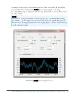
Note that in the zero-and-span window of
ECMon
, span
actual
is reported to the right of the
box where the user enters the span dewpoint temperature. The software calculates
span
actual
by taking into account the dewpoint temperature and current ambient
temperature and pressure. The equations used for this calculation may be found in
(p. 61). If drift (offset or gain) for CO
2
or H
2
O is excessive, it may
be time to replace the desiccant and CO
2
scrubber bottles (see
(p. 40)).
IRGASON® Integrated CO
2
/H
2
O Open-Path Gas Analyzer and 3D Sonic Anemometer
39
Summary of Contents for IRGASON
Page 1: ...Revision 08 2021 Copyright 2010 2021 Campbell Scientific Inc Product Manual ...
Page 73: ...IRGASON Integrated CO2 H2O Open Path Gas Analyzer and 3D Sonic Anemometer 69 ...
Page 74: ...IRGASON Integrated CO2 H2O Open Path Gas Analyzer and 3D Sonic Anemometer 70 ...
Page 75: ...IRGASON Integrated CO2 H2O Open Path Gas Analyzer and 3D Sonic Anemometer 71 ...
Page 77: ...IRGASON Integrated CO2 H2O Open Path Gas Analyzer and 3D Sonic Anemometer 73 ...
Page 78: ...IRGASON Integrated CO2 H2O Open Path Gas Analyzer and 3D Sonic Anemometer 74 ...
Page 79: ...IRGASON Integrated CO2 H2O Open Path Gas Analyzer and 3D Sonic Anemometer 75 ...
Page 80: ...IRGASON Integrated CO2 H2O Open Path Gas Analyzer and 3D Sonic Anemometer 76 ...
Page 81: ...IRGASON Integrated CO2 H2O Open Path Gas Analyzer and 3D Sonic Anemometer 77 ...
Page 82: ...IRGASON Integrated CO2 H2O Open Path Gas Analyzer and 3D Sonic Anemometer 78 ...
Page 83: ...D 3 Decarbite IRGASON Integrated CO2 H2O Open Path Gas Analyzer and 3D Sonic Anemometer 79 ...
Page 84: ...IRGASON Integrated CO2 H2O Open Path Gas Analyzer and 3D Sonic Anemometer 80 ...
Page 85: ...IRGASON Integrated CO2 H2O Open Path Gas Analyzer and 3D Sonic Anemometer 81 ...
Page 86: ...IRGASON Integrated CO2 H2O Open Path Gas Analyzer and 3D Sonic Anemometer 82 ...