background image

Table of Contents 

PDF viewers:  These page numbers refer to the printed version of this document.  Use the 

PDF reader bookmarks tab for links to specific sections. 

1. Introduction................................................................ 1
2. Precautions ................................................................ 1
3. Initial Inspection ........................................................ 1

3.1


Ships With ............................................................................................1


3.2


Calibration Certificate ..........................................................................1


4. QuickStart .................................................................. 2
5. Overview .................................................................... 4
6. Specifications ............................................................ 5
7. Installation ................................................................. 6

7.1


Siting ....................................................................................................6


7.2


Mounting to an Instrument Mount .......................................................7


7.2.1


Required Tools ..............................................................................7


7.2.2


Mounting Procedure ......................................................................7


7.3


Wiring to the Data Logger ...................................................................9


7.4


Programming ...................................................................................... 10


7.4.1


Input Range ................................................................................. 11


7.4.2


Multiplier .................................................................................... 12


7.4.3


Offset .......................................................................................... 12


7.4.4


Output Format Considerations .................................................... 12


8. Maintenance and Troubleshooting ......................... 12

8.1


Maintenance/Recalibrations ............................................................... 13


8.2


Troubleshooting ................................................................................. 13


Appendices 

A. Importing 

Short Cut

 Code Into 

CRBasic Editor

 ... A-1

B. Example Program .................................................. B-1

B.1


CR1000X Example Program ............................................................ B-1
 

Summary of Contents for CMP3

Page 1: ...CMP3 Pyranometer Revision 02 2020 Copyright 2006 2020 Campbell Scientific CSL I D 332...

Page 2: ......

Page 3: ...under guarantee or not Please state the faults as clearly as possible and if the product is out of the guarantee period it should be accompanied by a purchase order Quotations for repairs can be give...

Page 4: ......

Page 5: ...digital cell phones and aerials may also not be applicable according to your locality Some brackets shields and enclosure options including wiring are not sold as standard items in the European marke...

Page 6: ......

Page 7: ...beginning work Wear a hardhat and eye protection and take other appropriate safety precautions while working on or around tripods and towers Do not climb tripods or towers at any time and prohibit cl...

Page 8: ......

Page 9: ...6 Specifications 5 7 Installation 6 7 1 Siting 6 7 2 Mounting to an Instrument Mount 7 7 2 1 Required Tools 7 7 2 2 Mounting Procedure 7 7 3 Wiring to the Data Logger 9 7 4 Programming 10 7 4 1 Input...

Page 10: ...s 7 1 Pyranometer installation 6 7 2 CMP3 Schematic 10 Tables 7 1 Wire Colour Function and Data Logger Connection 10 7 2 Multipliers Required for Flux Density and Total Fluxes 12 CRBasic Example B 1 C...

Page 11: ...l Inspection Check the contents of the shipment If there is a shortage see Section 3 1 Ships With p 1 contact Campbell Scientific If any damage has occurred during transport immediately file a claim w...

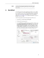
Page 12: ...It is included in installations of LoggerNet RTDAQ PC400 or PC200W The following procedure also describes programming with Short Cut 1 Open Short Cut and click Create New Program 2 Double click the da...

Page 13: ...b to see how the sensor is to be wired to the data logger Click OK after wiring the sensor 5 Repeat steps three and four for other sensors Click Next 6 In Output Setup type the scan rate meaningful ta...

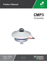
Page 14: ...l Scientific Cable length is user specified The CMP3 pyranometer is designed for continuous outdoor use Due to its flat spectral sensitivity from 300 to 2800 nm it can be used in natural sunlight unde...

Page 15: ...l Scientific CRBasic data loggers CR6 CR3000 CR1000X CR800 series CR300 series CR1000 6 Specifications ISO classification Second Class Response time 95 18 s Zero offset due to 200 W m2 thermal radiati...

Page 16: ...r you See Section 4 QuickStart p 2 for a Short Cut tutorial 7 1 Siting The CMP3 is usually installed horizontally but can also be installed at any angle including an inverted position In all cases it...

Page 17: ...hemisphere point the cable toward the North Pole 7 2 Mounting to an Instrument Mount 7 2 1 Required Tools Tools required for installation on a tripod or tower Small and medium Phillips screwdrivers 8...

Page 18: ...by tightening the U bolt nuts 3 Loosely mount the pyranometer on the mounting stand Do not fully tighten the two mounting screws CM225 Stand CM200 Series Crossarm U bolt Nuts CM225 mounting holes use...

Page 19: ...still correctly levelled and adjust as necessary 6 Attach the white plastic sun shield to the pyranometer 7 Route the sensor cable along the underside of the crossarm to the tripod tower and to the in...

Page 20: ...onnection Terminal Single Ended Data Logger Connection Terminal White Signal High U configured for differential input1 DIFF H differential high analogue voltage input U configured for single ended ana...

Page 21: ...ed measurement compare the results of single ended and differential measurements made under the same conditions Possible sources of electrical noise include power lines electric pumps or motors If the...

Page 22: ...e of thermopile detector sensors there will be some offset in dark conditions sometimes this offset can give negative light readings This offset varies with several factors such as rate of change of s...

Page 23: ...ientific recommends recalibrating every two years The sensor should be returned to Campbell Scientific the manufacturer or a calibration lab with facilities to calibrate radiation sensors 8 2 Troubles...

Page 24: ...yranometer 14 1 Check for the presence of strong sources of electromagnetic radiation radar radio 2 Check the condition and the connection of the sensor shield wire 3 Check the condition of the sensor...

Page 25: ...can now be edited for additional refinement Once the file is edited with CRBasic Editor Short Cut can no longer be used to edit the program it created 2 To add the Short Cut wiring information into t...

Page 26: ......

Page 27: ...e B 1 CR1000X Example Program CR1000X Declare Variables and Units Public Solar_Wm2 Public Solar_MJ Units Solar_Wm2 W m Units Solar_MJ MJ m Hourly Data Table DataTable Hourly True 1 DataInterval 0 60 M...

Page 28: ...If Solar_Wm2 0 Then Solar_Wm2 0 Calculate units in MJ where MJ m t 0 000001 m Solar_Wm2 from above and t 10 scan interval Solar_MJ Solar_Wm2 0 00001 Call Data Tables and Store Data CallTable Hourly Ca...

Page 29: ......

Page 30: ...cennes France Phone 0033 0 1 56 45 15 20 Email info campbellsci fr Website www campbellsci fr Germany Location Bremen Germany Phone 49 0 421 460974 0 Email info campbellsci de Website www campbellsci...

Reviews: