


Section 7. Camera Operation Using Web Browser Interface
7-32
7.6.3 Self Timed Capture2
Refer to the previous section as the settings and parameters are the same.
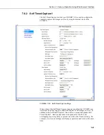
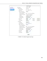
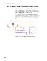
7.6.4 External Trigger
The External Trigger sub tab (see FIGURE 7-30) is used to configure the
camera to capture still images or video by using an external signal that is
applied to the External Trigger input line.
The External Trigger can be configured for an active HIGH signal or an active
LOW signal (see Digital I/O Settings). The Capture is triggered by the
transition from the inactive state to the active state. The minimum required
pulse period is 10 mSec. Preferably pulses should also be short in duration
(only a few seconds). The voltage levels are as follows:
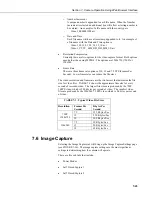
Low Level: < 0.65V (-20VDC Absolute Min)
High Level: >2.0 VDC (+20VDC Absolute Max)
Leaving the signal on the External Trigger in the active state will prevent the
camera from entering into a low powered state. If an external device is allowed
to keep the camera in its Fully On State, power consumption will be greatly
affected.
When the camera is fully on and no other process is taking place, the time from
the transition of the signal from inactive to active to the time a picture is
captured or video is started is typically less than 100 msec.
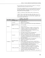
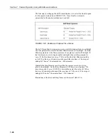
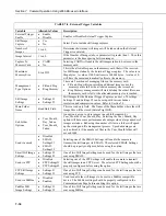
The description of the parameters for the External Trigger setup are outlined in
TABLE 7-8.
Summary of Contents for CC5MPX 6HULHV
Page 2: ......
Page 10: ...CC5MPX Table of Contents vi ...
Page 12: ...Section 1 Introduction 1 2 ...
Page 22: ...Section 3 Getting Started 3 8 FIGURE 3 7 CC5MPX Device Configuration Utility Settings Editor ...
Page 28: ...Section 4 Cables Wiring 4 6 ...
Page 36: ...Section 6 Camera Configuration 6 2 ...
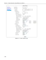
Page 72: ...Section 7 Camera Operation Using Web Browser Interface 7 36 FIGURE 7 31 Motion Detection Page ...
Page 84: ...Section 10 RS 485 Communications 10 2 ...
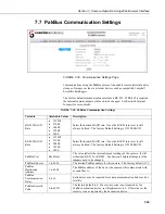
Page 86: ...Section 11 PakBus Communications 11 2 ...
Page 88: ...Section 12 Device Configuration Utility 12 2 FIGURE 12 2 Device Configuration Utility Screen ...
Page 90: ...Section 13 Image Quality 13 2 ...
Page 98: ...Section 15 Power Calculations and Timings 15 4 ...
Page 104: ...Section 17 Remote Image Retrieval 17 4 ...
Page 110: ...Section 19 Maintenance 19 4 FIGURE 19 5 Desiccant Location Location of Desiccant ...
Page 116: ...Section 21 System Limitations 21 2 ...
Page 122: ...Section 23 Quick Notes 23 4 ...
Page 129: ......


