


Section 5. Camera Hardware Description
5-2
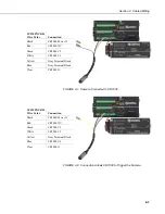
If a permanent Ethernet connection is required outdoors or if a connection is
required in wet or harsh locations, the CC5MPXCBL2-L Environmentally
Rated Ethernet cable must be used.
The maximum cable length for the Ethernet cable is 70 m (230 ft).
The CC5MPX does not support the PakBus communication
protocol over Ethernet.
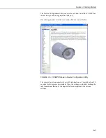
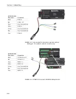
5.2 Power I/O Connection
The CC5MPXCBL1 cable must be attached to the Power I/O connector for
camera operation. It is the only means to supply power to the camera. The
connector that connects to the Power I/O connector provides a weather tight
connection.
When making the cable connection to the camera the notch positions should
always be lined up and care should be taken to not cross thread the connector.
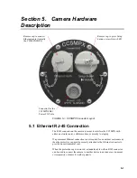
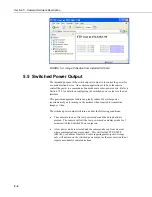
5.3 Setup Button/Status LED
The Setup button is located behind a protective metal cap on the camera. The
Setup button also contains an integrated Status LED for user feedback.
To access the LED unscrew the protective cap to expose the Button/LED. It is
highly recommended to place the protective cap back on for improved
environmental protection.
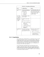
5.3.1 Status LED
The Status LED located in the center of the button provides some useful
diagnostic information about the camera. The following table describes the
LED behavior.
NOTE
Summary of Contents for CC5MPX 6HULHV
Page 2: ......
Page 10: ...CC5MPX Table of Contents vi ...
Page 12: ...Section 1 Introduction 1 2 ...
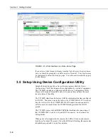
Page 22: ...Section 3 Getting Started 3 8 FIGURE 3 7 CC5MPX Device Configuration Utility Settings Editor ...
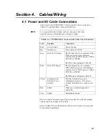
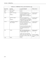
Page 28: ...Section 4 Cables Wiring 4 6 ...
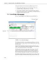
Page 36: ...Section 6 Camera Configuration 6 2 ...
Page 72: ...Section 7 Camera Operation Using Web Browser Interface 7 36 FIGURE 7 31 Motion Detection Page ...
Page 84: ...Section 10 RS 485 Communications 10 2 ...
Page 86: ...Section 11 PakBus Communications 11 2 ...
Page 88: ...Section 12 Device Configuration Utility 12 2 FIGURE 12 2 Device Configuration Utility Screen ...
Page 90: ...Section 13 Image Quality 13 2 ...
Page 98: ...Section 15 Power Calculations and Timings 15 4 ...
Page 104: ...Section 17 Remote Image Retrieval 17 4 ...
Page 110: ...Section 19 Maintenance 19 4 FIGURE 19 5 Desiccant Location Location of Desiccant ...
Page 116: ...Section 21 System Limitations 21 2 ...
Page 122: ...Section 23 Quick Notes 23 4 ...
Page 129: ......


