AM416 RELAY MULTIPLEXER
9
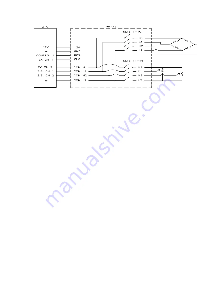
FIGURE 7. Wiring Diagram for Strain Gages and Potentiometers
(8) Additional Loops - Additional loops may be
used if sensors that require different
measurement instructions are connected to the
same multiplexer. In this instance, like sensors
are assigned to sequential input SETS. Each
group of sensors is measured in a separate
loop (steps 2 through 7, Figure 4). Each loop
contains clock and measurement instructions,
and all loops must reside between the
instructions that activate and deactivate the
AM416 (Steps 1 and 9).
The instruction sequence for control of an
AM416 is given on the following page. The
Program format is a product of EDLOG, a
datalogger program editor contained in CSI's
PC208 Datalogger Support Software.
5.2 MULTIPLE LOOP INSTRUCTION SEQUENCE
As shown above, the program for operation of
the AM416 is essentially the same for all CSI
dataloggers. To measure sensors of different
types, different measurement instructions may
be used within successive program loops. In
the following example, each loop is terminated
with Instruction 95, and the multiplexer is not
reset between loops. The following example
demonstrates measurement of two dissimilar
sensor types (i.e. strain gages and
potentiometers).
The program and accompanying wiring diagram
are intended as examples only; users will find it
necessary to modify both for specific
applications.
*
1
Table 1 Programs
01:
60
Sec. Execution Interval
ENABLES MULTIPLEXER
01:
P20
Set Port
01:
1
Set high
02:
1
Port Number
BEGINS STRAIN GAGE MEASUREMENT LOOP
02:
P87
Beginning of Loop
01:
0
Delay
02:
10
Loop Count
CLOCK PULSE
03:
P22
Excitation with Delay
01:
1
EX Chan
02:
1
Delay w/EX (units=.01sec)
03:
1
Delay after EX (units=.01sec)
04: 5000
mV Excitation
FULL BRIDGE MEASUREMENT INSTRUCTION
04:
P6
Full Bridge
01:
1
Rep
02:
3
50 mV slow Range
03:
1
IN Chan
04:
2
Excite all reps w/EXchan 2
05: 5000
mV Excitation
06:
1--
Loc [:STRAIN #1]
07:
1
Mult
08:
0
Offset
END OF STRAIN GAGE MEASUREMENT LOOP
05:
P95
End
Summary of Contents for AM416
Page 6: ...This is a blank page ...
Page 25: ...A 1 APPENDIX A AM416 STUFFING CHART AND SCHEMATICS ...
Page 26: ...APPENDIX A AM416 STUFFING CHART AND SCHEMATICS A 2 ...
Page 27: ...APPENDIX A AM416 STUFFING CHART AND SCHEMATICS A 3 ...
Page 28: ...APPENDIX A AM416 STUFFING CHART AND SCHEMATICS A 4 This is a blank page ...
Page 30: ...This is a blank page ...
Page 31: ...This is a blank page ...


