AM416 RELAY MULTIPLEXER
13
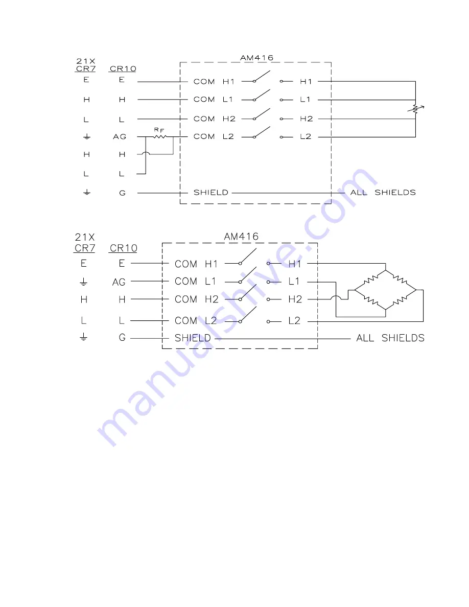
FIGURE 12. Four Wire Half Bridge Hook-up and Measurement
FIGURE 13. Differential Measurement with Sensor Excitation
6.4 FULL BRIDGE MEASUREMENTS
Sensor to Multiplexer wiring - Excitation,
ground, and the two signal leads may be
connected to one input SET (Figure 13).
Multiplexer to Datalogger wiring - COM
terminals are connected to a datalogger
excitation channel, a differential analog input
channel, and analog ground. Up to sixteen full
bridges may be multiplexed through the AM416.
6.5 FULL BRIDGES WITH EXCITATION
COMPENSATION
Sensor to Multiplexer wiring - In a six wire
measurement, two wires must bypass the
AM416. One solution is to multiplex the four
signal wires through the AM416, but bypass the
AM416 with excitation and ground. This means
that the sensors will be excited in common,
which causes a higher current drain, possibly
exceeding the current available from the
datalogger's excitation channels. Alternatively,
the excitation and ground leads may be
multiplexed through either an AM32 multiplexer
or an additional AM416. This allows the
sensors to be excited one at a time (Figure 14).
Multiplexer to Datalogger wiring - Four leads
from the COM terminals to two sequential
differential analog channels in the datalogger.
Excitation and ground are multiplexed by a
AM32 or AM416. Both multiplexers can be
reset and clocked by the same control ports
and/or excitation channels, which simplifies
programming.
Summary of Contents for AM416
Page 6: ...This is a blank page ...
Page 25: ...A 1 APPENDIX A AM416 STUFFING CHART AND SCHEMATICS ...
Page 26: ...APPENDIX A AM416 STUFFING CHART AND SCHEMATICS A 2 ...
Page 27: ...APPENDIX A AM416 STUFFING CHART AND SCHEMATICS A 3 ...
Page 28: ...APPENDIX A AM416 STUFFING CHART AND SCHEMATICS A 4 This is a blank page ...
Page 30: ...This is a blank page ...
Page 31: ...This is a blank page ...


