background image

Raven EDGE GPRS/EDGE AirLink Cellular Modem 


PN C2100 3 dBd Omni Directional Antenna 


PN L14454 9dBd Directional Yaggi Antenna 


PN L14453 Half-Wave Dipole Whip Antenna 

FIGURE 4.2-2.  Antennas for Use with the Raven Modems 

!


Power Supply (see power considerations). 

!


Environmental Enclosure— ENC 10/12, ENC 12/14, or ENC 16/18. 

4.3  Power Considerations 

!


A power cable included with the modem connects to the datalogger's 12 V 
or switched 12 V terminal.  Connection to the switched 12 V terminal 
allows the datalogger to switch power to the modem during scheduled 
transmission intervals if desired. 

!


When using the switched 12 V terminal, the modem can typically be 
powered with a BP12 battery, CH100 charger/regulator, and MSX10 solar 
panel. 

5.  Program the Raven EDGE Modem 

The following software is used to program the modem: 

Summary of Contents for Airlink Raven

Page 1: ...INSTRUCTION MANUAL Copyright 2008 Campbell Scientific Canada Corp Raven EDGE GPRS EDGE Airlink Cellular Modem March 2008...

Page 2: ...glect accidents of nature or shipping damage This warranty is in lieu of all other warranties expressed or implied including warranties of merchantability or fitness for a particular purpose CSC is no...

Page 3: ...irements for Raven EDGE 2 4 2 Datalogger Site Equipment 2 4 3 Power Considerations 6 5 Program the Raven EDGE Modem 6 5 1 Using ACE Manager to Configure the Modem 7 5 2 Dynamic IP Address 10 6 LoggerN...

Page 4: ...4 4 2 2 Antennas for Use with the Raven Modems 6 7 1 Wireless Ace status page showing communications with modem 17 B 1 Modem Back B 1 B 2 Modem Partially Slid from Case B 1 B 3 Tray Button B 2 B 4 Emp...

Page 5: ...the Internet A Dynamic IP address is assigned on a need to have basis A dynamic IP address is used with a service such as IP Manager Section 5 to translate a dynamic IP address to a domain name so th...

Page 6: ...o 250 mA Typical Current Drain at 12 Vdc 20 mA dormant connection idle for 10 to 20 seconds 130 mA transmit receive Operating Temperature Range 30 to 70 C 10 duty cycle limit above 60 C Operating Humi...

Page 7: ...not Rev 1 or newer as indicated on cable it is a CS I O cable only and will not work for RS 232 Connect the black SC12 cable between the datalogger and the SC932A Use a 9 pin serial cable or a blue r...

Page 8: ...gers with the PakBus Operating System SC932A interface connects the modem to the CS I O port recommended for dataloggers with the Mixed Array Operating System PN 18663 null modem cable connects the mo...

Page 9: ...n diameter o The L14454 9dBd Yagi Antenna is a higher gain antenna that should be aimed at the service provider s antenna The L14454 includes 10 feet of cable fitted with a TNC male connector for atta...

Page 10: ...ENC 16 18 4 3 Power Considerations A power cable included with the modem connects to the datalogger s 12 V or switched 12 V terminal Connection to the switched 12 V terminal allows the datalogger to...

Page 11: ...rs that support a maximum baud rate of 9600 e g CR10X The template file configures the modem to be compatible with CSI dataloggers The template files are available from Campbell Scientific s Website w...

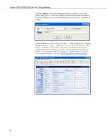
Page 12: ...lick OK to continue Click the Load icon in the Configuration panel When prompted for a template file name select ravengprs_115200 xml for dataloggers that support 115200 baud e g CR1000 or ravengprs_9...

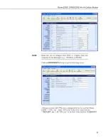
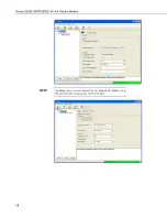
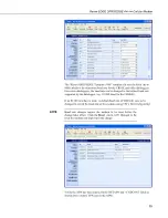
Page 13: ...ate supported by the datalogger e g 115200 for a CR1000 NOTE Click on EDGE HSDPA Group to get the following screen A Rogers account with VPN com is configured for an Access Point Name APN VPN com Ente...

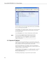
Page 14: ...ust also Reset the modem before the changes will take effect NOTE 5 2 Dynamic IP Address Data Plan accounts setup through Rogers are provided with a Dynamic IP address Dynamic IP addresses are granted...

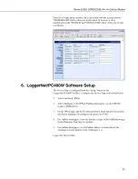
Page 15: ...gerNet PC400W Toolbar Configure the Device Map as described below 1 Select Add Root IPPort 2 Add a datalogger to the IPPort PakBus dataloggers e g the CR1000 require a PakBusPort 3 On the IPPort page...

Page 16: ...Raven EDGE GPRS EDGE AirLink Cellular Modem Preceding zeros are not entered in the Internet IP Address e g 070 218 074 247 is entered as 70 218 74 247 NOTE 12...

Page 17: ...a Dynamic Domain Name Server DDNS Section 5 The modem has to be configured using ACE Manager as described in Section 5 Modem settings have to be changed and the APN number entered using ACE Manager Se...

Page 18: ...irLink Cellular Modem The Device Port gets changed from the default 12345 to 6785 when the template file is loaded into the modem Section 5 The Device Port number gets entered with the IP address in L...

Page 19: ...y the datalogger e g 115200 baud for the CR1000 If an SC105 interface is used its default baud rate of 9600 will have to be changed to match the baud rate of the modem using CSI s DevConfig utility Ba...

Page 20: ...evice Map The IP address and Device Port settings are entered in LoggerNet as described in Section 6 Make sure the port number at the end of the IP address matches the port number of the modem The tem...

Page 21: ...the response from the datalogger did not make it back to the modem Check the interface between the modem and the datalogger If both values incremented the modem and the datalogger are communicating T...

Page 22: ...Raven EDGE GPRS EDGE AirLink Cellular Modem 18 This is a blank page...

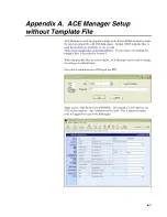
Page 23: ...p www campbellsci ca download html The procedure for sending the template files is described in Section 5 When the template files are not available ACE Manager can be used to change the settings descr...

Page 24: ...he baud rate needs to be configured to match a valid datalogger baud rate For a CR10X 9600 8N1 and for a CR1000 115200 8N1 Q Serial Port Flow Control This should be set to None V AT Verbose Mode Set t...

Page 25: ...Appendix A Wireless Ace Setup without Template File S0 TCP Auto Answer Set to On TCPT TCP Idle Timeout Set to a reasonable value like 2 min A 3...

Page 26: ...Appendix A Wireless Ace Setup without Template File A 4 This is a blank page...

Page 27: ...M To install the SIM you will only need a small phillips head screw driver Opening the Case 1 Unplug the modem power and all cables 2 Using a small phillips head screw driver remove the two screws on...

Page 28: ...y SIM Tray Inserting the SIM 6 Place the SIM into the tray and gently press to click it into place FIGURE B 5 SIM Tray with a SIM 7 Slide the tray back into the modem and gently press to click it into...

Page 29: ...the datalogger PPP enables the datalogger to send receive messages via email HTTP FTP to and from the datalogger and allows concurrent communications between networked dataloggers and LoggerNet The de...

Page 30: ...r PPP Use ACE Manager to configure the following PPP settings HOSTPRIVMODE 0 HOSTPRIVIP 192 168 1 1 Use WirelessAce to configure the following UDP setting MD 02 PPP Use AceManager to configure the fol...

Page 31: ...on to save the changes in the modem Click the Reset icon to restart the modem The other ways to reset the modem are by pressing the reset button on the front of the modem or removing the power from th...

Page 32: ...ect the Net Services tab The PakBus TCP Service Port default is 6785 This is the Port number that will follow the IP address for LoggerNet to communicate with the datalogger Using the Device Configura...

Page 33: ...Appendix C Configuring the Raven for PPP LoggerNet Settings Enter the IP address of the Raven and the PakBus TCP Service Port number of the datalogger e g 6785 as explained above C 5...

Page 34: ...RLF CHR 13 CHR 10 Public Result as String 100 Public AlarmTrigger As Boolean Public Message As String 250 Public EmailSuccess As Boolean BeginProg Scan 1 Sec 3 0 Battery Batt PanelTemp RefTemp 250 TCD...

Page 35: ...Appendix C Configuring the Raven for PPP C 7 This is a blank page...

Reviews: