Raven EDGE GPRS/EDGE AirLink Cellular Modem
7.2 Verify Connections at the Datalogger
Verify the modem is connected to 12 V and the Pwr led is on (green).
Check the Reg light on the modem. The Reg light should be solid green,
which indicates the modem is registered with the cellular network.
Make sure the antenna is properly connected and oriented. Signal strength
should be the -60 to -80.
An SC932A or SC105 interface is required to connect the modem to a
datalogger’s CSI/O port. The default settings for SC105 can be used with the
Raven EDGE when the modem is configured for 9600 baud (baud rate set by
the template file). If the baud rate is changed in the modem, the baud rate in
the SC105 will have to be changed to match that of the modem (SC105 settings
can be changed using CSI’s DevConfig utility).
Make sure the modem is connected to the “DCE Device” connector on the
SC932A, or the “Modem” connector on the SC105.
A null modem cable is required to connect the modem to a datalogger’s
RS-232 port. No other interface is required.
7.3 LoggerNet/PC400W Device Map
The IP address and Device Port settings are entered in LoggerNet as described
in Section 6.
Make sure the port number at the end of the IP address matches the port
number of the modem. The template file sets the port number to 6785.
Try adding a few seconds (no more than five seconds) of extra response time to
the datalogger or PakBus port.
For a PakBus datalogger, verify the PakBus address in the setup screen
matches that of the datalogger.
For networks with multiple PakBus ports, uncheck the ‘PakBus Port Always
Open’ options on all PakBus ports.
7.4 Using ACE Manager to Check Modem Communications
with Datalogger
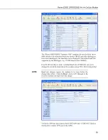
The modem’s “Host Serial Bytes Sent” and “Host Serial Bytes Received”
windows can indicate whether or not the modem is communicating with the
datalogger.
Establish a connection with the modem through the cellular network using
ACE Manager (click on the Modem menu item, Connect, UDP. Enter the IP
address, and click OK). Go to the Status group and note the “Host Serial Bytes
Sent” and “Host Serial Bytes Received” values (Figure 7-1). Try connecting
with the datalogger using LoggerNet/PC400W. If a connection cannot be
established, close LoggerNet and reconnect with ACE Manager and compare
the current values with the previous values.
16


