background image

10

Operating Instructions and Parts Manual

www.chpower.com

Assembly

tooLS requIreD For ASSeMbLy

u

  Screwdriver

u

  (2) Wrenches

hAnDLe ASSeMbLy

1.  Slide handle into shroud holes until 

the holes of the handle line up with 
the holes of the tank bracket.

2.  Insert and tighten screws to hold the 

handle in place.

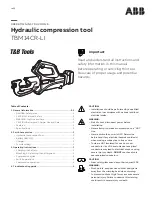
InFLAtIon hoSe ASSeMbLy

1.  Thread the coil hose into the fitting 

on the shroud. Use 2 adjustable 
wrenches, as shown in Figure 10, to 
tighten the connection.

2.  Screw blow gun onto the end of the 

coil hose.

Once the recoil hose and blow gun are 
attached, make sure no pressure is in 
tank before replacing. Recoil hose and 
blow gun must be installed for unit to 
operate properly.

Installation

LoCAtIon

When assembled, the tank must sit level 
to allow the tank to drain properly.

It is extremely important to install the 
compressor in a clean, well ventilated 
area where the surrounding air 
temperature will not be more than 100°F.

A minimum clearance of 18 inches 
between the compressor and a wall is 
required because objects could obstruct 
air flow.


Do not locate the 

   compressor air inlet 

near steam, paint spray, sandblast areas 
or any other source of contamination. This 
debris will damage the motor.

Figure 9 - handle assembly 

Figure 10 - Inflation hose assembly 

Summary of Contents for Reference Design

Page 1: ...O DO IT LIKE A PRO Visit us at chpower com Rapid Inflation Air Compressor Operating Instructions and Parts Manual WL6700 Series Fran aise Page 20 Espa ol p gina 40 2009 Campbell Hausfeld Scott Fetzer...

Page 2: ...To Know Your Compressor 9 Unpacking 9 Recommended Uses for this Compressor 9 Assembly 10 Tools Required for Assembly 10 Handle Assembly 10 Inflation Hose Assembly 10 Installation 10 Location 10 Wheel...

Page 3: ...Running HP 1 7 ISO 1217 Free Air CFM 3 8 90 psi ISO 1217 Free Air CFM 5 6 40 psi ISO 1217 Tank Capacity gallons 18 22 26 or 30 Volts Phase 120 V single Amp Draw 15 Max Working Pressure 150 Max Duty Cy...

Page 4: ...sed existing warranties shall be voided and Campbell Hausfeld disclaims any liability whatsoever for any loss personal injury or damage General a To reduce the risks of electric shock fire and injury...

Page 5: ...work area clean and well lighted Cluttered benches and dark areas increase the risks of electric shock fire and injury to persons b Keep bystanders children and visitors away while operating Distract...

Page 6: ...requirements established by the American National Standards Institute Standard B19 3 1991 Safety Standard for Compressors for Process Industries Contact your air compressor manufacturer for informatio...

Page 7: ...l assembly steps are complete and until you have read and understood the entire operator s manual u To reduce the risk of injury if any parts are missing do not attempt to assemble the air compressor...

Page 8: ...edal On Off Switch Used to turn the compressor on and off Motor Protection If the unit is over worked a thermal switch will shut unit off If this happens turn unit OFF the ON OFF Switch wait 30 minute...

Page 9: ...lers Intermittent Use Short powerful bursts Air chisels Air drills Automotive spray guns Die grinders Tools Not Recommended Cut off tools Dual action sanders Highspeed sanders Jitterbug sanders Straig...

Page 10: ...and blow gun are attached make sure no pressure is in tank before replacing Recoil hose and blow gun must be installed for unit to operate properly Installation Location When assembled the tank must s...

Page 11: ...ossible risk of electrical shock Do not use a grounding adapter with this product 2 If repair or replacement of cord or plug is necessary do not connect grounding wire to either flat blade terminal Th...

Page 12: ...105 located as near to the gun as possible will help eliminate this moisture This compressor can be used for general inflation as well as intermittent duty air tool usage For inflation purposes this c...

Page 13: ...it operates properly 2 Attach blow gun to the other end of the recoil hose The blow gun should ALWAYS be connected to the recoil hose 3 To inflate balls rafts etc attach inflation needle or nozzle to...

Page 14: ...glasses pull the ring on the safety valve to release pressure from compressor tank Use your other hand to deflect fast moving air from being directed toward your face 3 The safety valve should automat...

Page 15: ...Thermal overload protector This compressor is equipped with an automatic reset thermal overload protector which will shut off motor if it becomes overheated If thermal overload protector shuts motor...

Page 16: ...connections fittings tubing etc 1 Check all connections with soap and water solution Tighten or remove and apply pipe dope or pipe tape to the threads then reassemble 2 Open tank drain 2 Close drain...

Page 17: ...Motor assembly kit Includes 2 3 6 7 10 12 14 WL019100SJ 1 2 Cylinder gasket 1 3 Intake valve 1 4 Valve plate 1 5 Exhaust valve 1 6 Head gasket 1 7 Exhaust valve gasket 1 8 Head WL010500AV 1 9 Piston...

Page 18: ...Hausfeld Serial number if any Attn Customer Service Part description and number as shown in parts list 100 Production Drive Harrison OH 45030 U S A Figure 21 Repair Parts Illustration for Rapid Infla...

Page 19: ...tch ST196400AV 1 33 On Off Pedal WL044500AV 1 34 Eccentric Cover WL044400AV 1 35 Motor Bracket BA018300AV 1 Ref Part No Description No Qty Ref Part No Description No Qty 36 Wheel 10 OD Black Hub WA004...

Page 20: ...Accident purchaser s abuse neglect or failure to operate products in accordance with instructions shall also include the removal or alteration of any safety devices If such safety devices are removed...

Reviews: