Operation Manual
Turbocharging
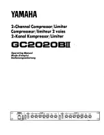
ABB Turbo Systems Ltd
ABB Turbo Systems Ltd
CH 5401 Baden
Type
TPL65-A33
HT562837
n
Mmax
503
t
Mmax
600
n
Bmax
486
t
Bmax
600
1/s
°C
01230
35
50
50
Year
2013
made in Switzerland
Application according to
the Operation Manual
kg
HZTL2498 English
TPL65-A33
Original Operation Manual