Notas
Instrucciones de montaje y lista de piezas
PW1676
Max Pressure with
Effective Pressure
Maximum
Motor Power
Maximum Inlet
Unit
Model
Standard Lance
w/Turbo Lance
Capacity
(Single Phase)
Voltage
Water Temperature
Weight
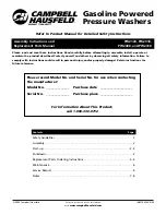
Electric Pressure
Washer
Please read and save these instructions. Read carefully before attempting to assemble, install, operate or maintain the product described.
Protect yourself and others by observing all safety information. Failure to comply with instructions could result in personal injury and/or prop-
erty damage! Retain instructions for future reference.
Specifications
PW1676
1300 psi
1750 psi
1.9 GPM
14.5 Amps
120 V
100˚F
39 lbs.
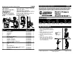
Installation Instructions
Assembly Instructions and Parts List
PW1676
NOTE: REFER TO PRODUCT MANUAL FOR
ALL SAFETY INSTRUCTIONS
Tools Required for Installation:
●
Flat Screwdriver
●
Hammer/Mallet
●
Adjustable Wrench
1. Set plastic spacer (included in parts
pack) on workbench (Figure 1).
2. Place “star shaped” retaining ring on
the spacer (tangs pointing down)
(Figure 2).
3. Tap the retaining ring onto the axle
(Figure 3 & 4).
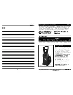
4. Put both wheels on axle,
solid sides
together
(Figure 5).
5. Attach opposite ring in the same
manner (Figure 6).
6. Slide wheels out and snap axle into
place on the underside of body
(Figure 7).
7. Snap wheel covers on the wheel.
8. Attach foot to front of pressure
washer body (Figure 7).
9. Hook up chemical suction hose to the
tip on the bottom of the handle
(Figure 8).
10. Attach black handle with enclosed
screws and washers (Figure 9).
Figure 1
IN457000AV 4/00
© 2000 Campbell Hausfeld
For parts, product & service information
visit
www.campbellhausfeld.com
U
L
Approved
#7P64
Figure 2
Figure 4
Figure 5
Figure 6
Figure 7
Figure 9
Figure 8
Figure 3
Solid
Sides