5
AT802000, CHG00189
www.campbellhausfeld.com
3. Make sure the trigger
and work contact
element (WCE) move
freely up and down
without sticking or
binding.
4. Reconnect air
supply to the
tool.
5. Depress the Work
Contact Element
(WCE) against the
work surface without
pulling the trigger.
The tool
MUST NOT
OPERATE
. Do not use the tool if it
operates without pulling the trigger.
Personal injury may result.
6. Remove the tool from
the work surface.
The Work Contact
Element (WCE) must
return to its original
down position.
The tool
MUST NOT OPERATE
.
Do not use the tool if it operates
while lifted from the work surface.
Personal injury may result.
7. Pull the trigger
and depress the
work contact
element (WCE)
against the
work surface. The tool
MUST NOT
OPERATE
.
8. Depress the
Work Contact
Element (WCE)
against the
work surface.
Pull the trigger. The tool
MUST
OPERATE
.
An
improperly
functioning
tool
must not be used. Do not actuate the
tool unless the tool is placed fi rmly
against the work piece.
3. Use 1/4 inch
air hoses with
a minimum
working
pressure of
150 PSI. Use 3/8 inch air hoses for
50 ft. run or longer. For better
performance, install a 3/8 inch quick
plug (1/4 inch NPT threads) with an
inside diameter of .315 inch (8mm)
on the tool and a 3/8 inch quick
coupler on the air hose.
4. Use a pressure regulator on the
compressor, with an operating
pressure of 0 -125 PSI. A pressure
regulator is required to control
the operating pressure of the tool
between 60 and 100 PSI.
SINGLE SEQUENTIAL MODE
This mode requires
the trigger to be
pulled each time a
fastener is driven.
The tool can be
actuated by depressing the WCE against
the work surface followed by pulling
the trigger.
The trigger must be released to reset
the tool before another fastener can be
driven.
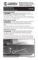
CHECKING THE WORK CONTACT
ELEMENT (WCE)
Check the operation
of the Work Contact
Element (WCE) trip mechanism before
each use. The WCE must move freely
without binding through its entire
travel distance. The WCE spring must
return the WCE to its fully extended
position after being depressed. Do
not operate the tool if the WCE trip
mechanism is not operating properly.
Personal injury may occur.
1. Disconnect the
air supply from
the tool.
2. Remove all
fasteners from
the magazine
(see Loading/
Unloading).
Operating the Tool
LUBRICATION
This tool requires lubrication before
using the tool for the first time and
before each use. If an inline oiler is
used, manual lubrication through the
air inlet is not required on a daily basis.
The work surface
can become
damaged by excessive lubrication.
Proper lubrication is the owner’s
responsibility. Failure to lubricate
the tool properly will dramatically
shorten the life of the tool and void the
warranty.
1. Disconnect the
air supply from
the tool to add
lubricant.
2. Turn the tool so the
air inlet is facing up.
Place 4-5 drops of 30
W non-detergent oil
into air inlet. Do not
use detergent oils, oil
additives, or air tool oils. Air tool oils
contain solvents which will damage
the tool's internal components.
3. After adding oil, run
tool briefly. Wipe off
any excess oil from
the cap exhaust.
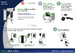
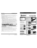
RECOMMENDED HOOKUP
The illustration below shows the
recommended hookup for the tool.
1. The air
compressor
must be able
to maintain a
minimum of
60 PSI when the tool is being used.
An inadequate air supply can cause
a loss of power and inconsistent
driving.
2. An oiler can be
used to provide oil
circulation through
the tool. A filter can
be used to remove
liquid and solid
impurities which can rust or “gum
up” internal parts of the tool.
60 psi
min.
100 psi
max.
150 psi WP
1/4 inch I.D.
Movement
1
2