


CAMON C500 Stump Grinder
CAMON C500 Stump Grinder
CAMON-C500/11.11/4
CAMON-C500/11.11/5
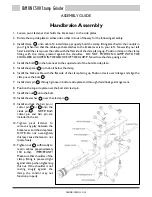
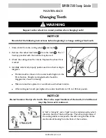
Handbrake Assembly
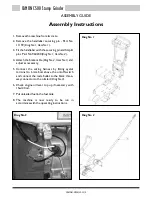
1. Loosen pivot fastener that holds the brake lever to the side plates.
2. Rotate the top side plate to either side so that it is out of the way for the following assembly.
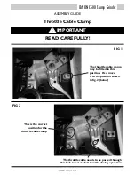
3. Install clamp onto cable. To install clamp properly, hold the clamp fitting attached to the conduit in
your right hand so that the cable eye that attaches to the brake lever is to your left. Now with your left
hand install the clamp over the cable with the flat side of the clamp facing up. Position clamp on the clamp
fitting with the clamp pressed against the shoulder. DO NOT POSITION CLAMP WITH THE
SHOULDER LOCATED IN THE GROOVE OF THE CLAMP. Now close the clamp using a vice.
4. Install the bolt in the hole next to the squared end of the bottom side plate.
5. Install the spacer on the bolt below the clamp.
6. Install the brake cable with the flat side of the clamp facing up. Position clevis over linkage and align the
clamp over the bolt .
7. Install clevis pin through groove in bottom side plate and through clevis/linkage arrangement.
8. Position the top side plate over the bolt and clevis pin.
9. Install the nut onto the bolt.
10. Install the washer over the clevis pin .
11. Install and lock the hair pin or
cotter pin or onto the
clevis pin . NOTE: Both
cotter pin and hair pin are
included in the kit.
12. Tighten pivot fastener to
remove any play between the
brake lever and the side plates.
NOTE: Do not over-tighten,
this may cause the lever to not
rotate freely.
13. Tighten nut sufficiently to
retain cables (approximately
150 in-Ibs). IMPORTANT!
Make sure that shoulder of the
clamp fitting is pressed tight
against clamp when tightening
this nut. If the shoulder is not
resting snugly against the
clamp, the control may not
function properly.
ASSEMBLY GUIDE
OPERATION
WARNING!
!
Operation
Before operating, please consult the SAFETY section for vital information relating to the
operation of this powerful machine.
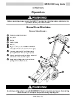
Know Your Machine
General Identification
WARNING!
!
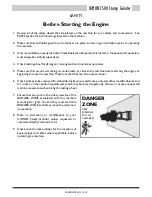
A rotating cutting wheel is very DANGEROUS! Stand at controls and ensure that cutting
wheel comes to a complete stop before doing anything else.
1
2
7
8
9
3
6
5
4
Operator presence control
Handlebar
Engine
Cutter wheel
Wheels
Engine switch
(see the NORMAL START-UP
section for instructions on how to start engine)
Throttle
(move forward to increase engine
speed, pull back to decrease engine speed)
Choke
(see the NORMAL START-UP section for
instructions on how to start engine)
Brake lever
(pulling back will set the brake,
pushing it down will release it)
1
2
3
4
5
6
7
8
9
1
2
3
4
5
6
7
8
7
6
6
1


