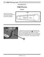
background image

V-Belt Tension

Check

Drive belts are properly 
tensioned when 5kg of pressure 
at the centre of the span 
produces 4mm deflection.

To adjust tension, loosen the engine mounting bolts, loosen 
the lock nut on the tensioning screw      on the front of the 
frame.  Turn the tensioning screw clockwise to increase 
tension and anti-clockwise to decrease tension.  After proper 
belt tension is obtained, tighten lock nut on tensioning screw 
and all engine mounting bolts.  Recheck alignment of pulleys.

5kg

Deflection = 4mm

1

1

MAINTENANCE

MAINTENANCE

CAMON C500 Stump Grinder

CAMON C500 Stump Grinder

CAMON-C500/11.11/18

CAMON-C500/11.11/19

Storing the Machine

Preparing the Machine for Storage

Store the machine in a dry protected place.  If the machine must be stored outside, cover it with a 
waterproof canvas or other material.

Clean all grease, dirt, mud, and other foreign matter from the machine.  Wash the machine.  Start and 
operate the machine to help get rid of puddled or excess water.  To inhibit rusting, paint all exposed 
surfaces.

Remove all drive belts, and store in wrapped condition.  Spray grooves of belt sheaves with anti-corrosive 
agent.

Information on preparing the engine for storage, is contained in the “Storage” section of the Honda 
Operation Manual, shipped with this machine.

Check your machine for any worn or broken parts at this time.  By ordering and installing replacement 
parts now, you can avoid unnecessary delays when you remove the machine from storage.

Removing the Machine from Storage

Remove all coverings.

After prolonged storage, inspect wheels and brakes.  Check tyres for proper inflation.

Check fuel lines for deterioration, and replace as necessary.  Tighten all nuts, bolts and replace fuel filter.

Information on removing the engine from storage is contained in the “Storage” section of the Honda 
Operation Manual, shipped with this machine.

Wipe off any anti-corrosive agent from grooves of belt sheaves and remount the belts.

Check the tension of the belts.

Check the machine in accordance with the “Before Starting the Engine” as found on page 13 of these 
Operating Instructions.

Summary of Contents for C500

Page 1: ...C500 STUMP GRINDER Operating Instructions Before commissioning the machine read operating instructions and observe warning and safety instructions...

Page 2: ...lTips for Operating Machine Page 10 While in Operation Page 11 SAFETY Normal Shutdown Procedure Page 12 Emergency Shutdown Procedure Page 13 Before Starting the Engine Page 13 MAINTENANCE BrakeAdjustm...

Page 3: ...work clear the work area of any objects that could damage the machine DO NOT allow children or anyone uninstructed to operate the machine KEEP ANIMALS AWAY o DO NOT use on slopes or banks of more tha...

Page 4: ...Diag No 2 Item No 1 and adjust as necessary 5 Connect the wiring harness by fitting eyelet terminal to 6mm bolt above the on off switch and connect the male bullet to the black three way connector to...

Page 5: ...s position If so move it to the position shown in fig 2 below This is the correct position for the throttle cable clamp The throttle cable needs to be passed through this hole to ensure full throttle...

Page 6: ...e spacer on the bolt below the clamp 6 Install the brake cable with the flat side of the clamp facing up Position clevis over linkage and align the clamp over the bolt 7 Install clevis pin through gro...

Page 7: ...trols and ensure that cutting wheel comes to a complete stop before doing anything else 1 2 7 8 9 3 6 5 4 Operator presence control Handlebar Engine Cutter wheel Wheels Engine switch see the NORMAL ST...

Page 8: ...maintenance inspections and services as found necessary before operating the machine Starting the Engine Read and understand the SAFETY section of this manual in its entirety before proceeding Do not...

Page 9: ...ection should be considered as it influences the direction in which dust and wood chips will be directed Never operate the machine after dark Night time operation will not allow the operator to see th...

Page 10: ...iscussed in this OPERATION section Keep everyone away when cutting wheel is ON Lock the brake by pulling back the brake lever 2 Remove roots Make sure the throttle is set to FAST The cutter wheel is t...

Page 11: ...ing away of wood with each sweep 2 Raise and lower the cutter wheel between sweeps as needed by lowering and raising the control handle Roll the machine forward and back by pushing and pulling on the...

Page 12: ...oots it may be more effective to do so before rather than after cutting the stump 3 Should the chip build up become excessive when cutting shut off the machine wait for the cutting wheel to stop rotat...

Page 13: ...your person The machine may slide toward you or you may fall toward the machine Cut only on a slope from the side Never O attempt to cut on a slope exceeding 15 8 Never operate the machine after dark...

Page 14: ...position 2 Release operator presence control A rotating cutting wheel is very DANGEROUS Stand at controls and ensure that cutting wheel comes to a complete stop before doing anything else 3 Set park...

Page 15: ...ine before starting the engine or beginning to move the machine Make sure that the area is free of personnel 6 Check stumps to be removed for embedded nails wire metal fence posts and other metallic o...

Page 16: ...lock nuts on hub at lower end of cable Adjust lock nuts as necessary and re tighten 1 1 For fine adjustment turn brake lever knob clockwise one revolution while brake is released then check operation...

Page 17: ...rding to diagrams Position teeth as shown in the cutter teeth diagram in the Parts Section Straight and angled teeth should be staggered as shown in drawing Make sure teeth are placed in co ordinance...

Page 18: ...a qualified machinist for obtaining a proper edge and to avoid injury Tooth Sharpening Guidelines 1 Obtain an unused tooth for comparison 2 Discard any tooth that has lost more than 3mm of original bi...

Page 19: ...the bearing seals Use extreme caution when using a high pressure or high volume grease gun Walk Around Inspection 1 Inspect and remove any chip or residue build up in and around the engine 2 Be sure...

Page 20: ...n the tensioning screw on the front of the frame Turn the tensioning screw clockwise to increase tension and anti clockwise to decrease tension After proper belt tension is obtained tighten lock nut o...

Page 21: ...nda Operation Manual shipped with this machine Check your machine for any worn or broken parts at this time By ordering and installing replacement parts now you can avoid unnecessary delays when you r...

Page 22: ...spection X X X X X X X Engine leaks check X Engine oil change X X X Engine mounts check X X X X X V belt tension check X X X X X Brake adjust X X Brake lining check X Tyre condition check X Tyre press...

Page 23: ...CAMON C500 Stump Grinder CAMON C500 11 11 21...

Page 24: ...Sovereign Centre Victoria Road Burgess Hill RH15 9LR T 44 0 1444 247689 F 44 0 1444 871612 W www tracmaster co uk E info tracmaster co uk Tracmaster Ltd 2011 Specifications are subject to change witho...

Reviews: