background image


17


Chapter


6


Fan


6.1.


Commissioning


Commissioning


may


only


be


carried


out


by


trained


professionals.


The


trained


professional


in


question


must


assure


him

‐ 

or


herself


that


the


fan


is


in


perfect


working


order.


The


commissioning


regulations


for


electrical


ma

chines


must


be


observed.


Check


the


safety


devices.


Turn


on


the


main


switch.


Switch


on


the


fan.


The


fan


may


only


be


switched


on


once


the


relevant


ductwork


has


been


connected.


This


ensures


that


there


is


sufficient


system


resistance


during


the


run

up


phase.


When


commissioning


the


fan


for


the


first


time,


check


the


direction


of


rotation


of


the


motor.


CAUTION


The


fan


must


turn


in


the


direction


indicated


by


the


arrow.


The


direction


of


rotation


can


be


checked


using


a


field


of


rotation


tester.


Check


the


power


consumption.


The


permitted


power


consumption


of


the


motor


must


not


be


exceeded.


6.2.


Shutdown


Switch


off


the


fan.


Turn


the


main


switch


to


the


"OFF"


position


and


secure


so


that


it


cannot


be


turned


back


on


by


an


unauthorized


person.


6.3.


Startup


behavior


of


fans


There


must


be


a


sufficient


acceleration


torque


over


the


entire


startup


range


up


to


the


nominal


speed


to


enable


the


run

up


of


the


fan.


This


is


not


always


the


case


for


medium

‐ 

and


high

pressure


fans.


In


such


cases,


the


fan


can


be


run


up


against


a


closed


throttle


device.


Power


supply


units,


switching


devices,


monitoring


devices


(if


present),


and


cable


cross

sections


must


be


dimensioned


and


checked


by


the


customer


with


regard


to


their


startup


type


and


time


and


their


current


peaks.


6.4.


Startup


for


direct


activation


In


the


case


of


the


direct


activation


of


the


fan,


the


motor


develops


a


high


torque


at


a


high


starting


current.


The


starting


current


during


the


startup


phase


is


between


5


and


8


times


the


nominal


current


depending


on


the


impeller


class

.


This


high


power


consumption


must


be


taken


into


account


when


choosing


the


fuses.


Summary of Contents for Handte Vortex Dual

Page 1: ...Original Operating Instructions Fig Handte Vortex Dual separator Handte Vortex Dual For inflammable dry metal types of dust Date 04 13 2015 Version V 1 1 Language English ...

Page 2: ......

Page 3: ...1 Place of installation 11 4 2 Water connection 11 4 3 Electrical connection 12 4 4 Suction line 13 4 5 Exhaust line 14 4 6 Recirculation of clean air into room 15 4 7 Humidification of air 15 Chapter 5 Commissioning 16 Chapter 6 Fan 17 6 1 Commissioning 17 6 2 Shutdown 17 6 3 Startup behavior of fans 17 6 4 Startup for direct activation 17 Chapter 7 Operation 18 Chapter 8 Decommissioning 19 Chapt...

Page 4: ...3 ...

Page 5: ...ersonnel are the individuals responsible for transportation installation commis sioning operation maintenance cleaning and troubleshooting for the de vice 1 3 Signs and symbols used in this operating manual Bulleted lists Items in bulleted lists are introduced by bullet points Point 1 Point 2 Instructions with a defined order Instructions that must be carried out in a defined order are sequentiall...

Page 6: ... valid national legislation in the country of use The user is responsible for en suring that such legislation is observed 1 6 Improper use Camfil APC assumes no liability for improper use The device must not be used to extract and separate potentially explosive gases vapors and or hybrid mixes The device must never be used without water In addition the following constitute improper user Any unauth...

Page 7: ...the dangerous situation is not averted severe injury or even death may occur nCAUTION This indicates a possibly dangerous situation If the dangerous situation is not averted severe injury may occur CAUTION This indicates a possibly damaging situation If this situation is not averted the product or something in the vicinity of the collector could be damaged Example nCAUTION Rotating fan impeller Ri...

Page 8: ...operator may only operate the device if it is in a fault free state The operator must install the device in accordance with the installation plan and requirements The operator must use appropriate instructions and checks to ensure the cleanliness and tidiness of the workplace where the system is situ ated The user must immediately inform the operator of any changes includ ing changes in operating ...

Page 9: ...ical safety specifications Transportation Regulations Protection measures storage and handling Measures for accidents and fires Toxicology specifications Ecological specifications This is particularly true with regard to the proper disposal of operating re sources and additives Residual risks For residual risks arising from work with the device and measures to be im plemented in order to avert dan...

Page 10: ... gas flow is deflected Due to inertia the particles move towards the surface of the liquid and are bound or accumulate there In the scrubber the dust carrying liquid particles and air are separated by means of centrifugal force The cleaned air is blown out through the clean gas port of the device The scrubbing liquid containing the accumulated dust particles flows downwards into the sludge tank wh...

Page 11: ...r horizontal position on a pallet The device can be transported using a forklift the transportation pallet remains under the device or by means of ropes attached to the eye bolts or crane eyes CAUTION Damage to protruding device parts When placing the crate pallet onto the forklift pay attention to protruding parts of the device Lifting the device When lifting the device out of the transportation ...

Page 12: ...e The device must be installed in a vertical position that enables it to work in a fault free manner Make sure that the air inlet and outlet ports are in the right place Device attachment Following alignment the device must be bolted to the substructure Floor drainage The installation room should have a floor drainage system to allow escaping water to drain away safely The operator must check whet...

Page 13: ...igh starting torque at a high starting current this can be up to 5 to 8 times the nominal current depending on the impeller class These values must be taken into consideration when choosing the fuses Potential equalization For the extraction of non conductive dusts the device each individual ductwork part all dust collection elements and flexible tubes must be grounded by means of potential equali...

Page 14: ...are recommended before and after pipe branches If a sound absorber is installed in the ductwork cleaning openings are re quired before and after it Shut off valves We recommend that you install vertical manually operated shut off valves directly on the individual collection points in order to adjust the air sub flows Attachment of pipes The ductwork must be secured using suitable means of attachme...

Page 15: ... The ductwork must not be propped up by the device Potential equalization In the case of the extraction of non conductive dust the exhaust line must be grounded by means of potential equalization Seals must be electrically conductive Otherwise potential equalization sys tems must be used throughout the ductwork system The connection of multiple potential equalization systems to a single at tachmen...

Page 16: ...fication of air Formation of condensate The exhaust air will probably require humidification depending on the tem perature and relative humidity of the exhaust air You should assume hu midification of the exhaust air of around 90 in the device The air volume of the work room should be at least of the air quantity re circulated by the device per hour so that when the device is working at full retur...

Page 17: ...ts Adjust the ductwork system Make sure that the suction levels at the individual collection points are equal Make sure that the flow speed in horizontal pipe sections is around 60 65 ft s Adjust the level regulator in line with the operational water level Switch on the fan See Fan CAUTION Too many startup cycles per hour Our motors are in Class S1 and are designed for continuous operation Too man...

Page 18: ...st not be exceeded 6 2 Shutdown Switch off the fan Turn the main switch to the OFF position and secure so that it cannot be turned back on by an unauthorized person 6 3 Startup behavior of fans There must be a sufficient acceleration torque over the entire startup range up to the nominal speed to enable the run up of the fan This is not always the case for medium and high pressure fans In such cas...

Page 19: ...APC please observe the pro vided operating manual Water supply When the device system is in use the water supply should be checked reg ularly CAUTION Malfunction due to closed water supply If the water supply is switched off during operations this results in a water shortage in the case of a mechanical level regulator This is not signaled As a result the dust separation process is significantly re...

Page 20: ...econds to remove any accumu lations of dust from the ductwork system Place the main switch into the OFF position Clean the inside of the device thoroughly Decommissioning for a longer period of time In the case of the decommissioning of the device for a longer period of time the following measures must be implemented Switch off the working machinery Allow the device to run for another 10 seconds t...

Page 21: ...level regulator Soiling of ventilator impeller Clean and rebalance if necessary Fan running in wrong direction Reverse the motor Defective compensator Replace the compensator 02 Dust escaping from air outlet port Heavily reduced suction performance Check the valve positions the air quantity must not be excessively throttled Water level too low Check the discharge valve level regulator and water su...

Page 22: ... cool ing system Remove the blockage Loose or defective connection collars on exhaust pipes Tighten the hose clips and replace the defective collars Water level too high Check the level regulator Lower the water level Motor surface heavily soiled insuffi cient heat dissipation Clean the motor surface make sure that the cooling fins are clean 06 Fan does not start run ning Drive motor connected up ...

Page 23: ...vice and accumulates as sludge is to be stored and disposed of Regulations on the storage of specific types of dust must be observed in particular Changing the water It is vital to ensure the regular replacement of the water in the device There are the following types of water change Discontinuous water change Continuous water change For relevant information on the required water quality please se...

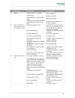
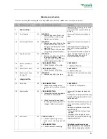
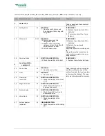
Page 24: ... INSPECTION 5 Check the state of the collar IF NECESSARY 1 Replace the collar 1 5 Water return hose M VISUAL INSPECTION 2 Check the state of the hose IF NECESSARY 3 Replace the hose 1 6 Water return pipe for size 7 M CLEANING 4 Remove any dirt in the pipe The lid must be removed to enable cleaning 2 Integrated fan 2 1 Entire fan W VISUAL INSPECTION 1 Check for operating noises make sure it is runn...

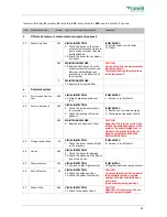
Page 25: ...e observe the instructions in our brochure on water as an oper ating resource 3 3 Drain ball valve M FUNCTIONAL INSPECTION 15 Check the mobility of the ball IF NECESSARY 1 Replace the defective ball valve 4 Level regulation equipment 4 1 Control box W CLEANING 2 Clean the control box Once cleaning has been completed and the scrubber has been filled with water again the level regulator setting must...

Page 26: ...Check the inside and outside for corrosion 3 Check the ductwork for dust deposits IF NECESSARY 4 Rectify any corrosion damage 5 Eliminate any deposits of dust 6M MAINTENANCE WORK 6 Remove any deposits of dust CAUTION Deposits of dust in the suction line reduce the extraction power of the system The overall weight can in crease to the extent that the sus pension system breaks and the ductwork falls...

Page 27: ... 2 Extraction hoods M CLEANING 19 Clean the inside and outside of the hoods 20 Clean the integrated intake grate optional CAUTION Integrated intake grates can gradu ally become clogged due to sucked in particles This reduces the amount of air that is sucked in The air speed in the ductwork sys tem drops and dust accumulates in the suction pipe system 7 3 Work room M Y CLEANING 21 All surfaces wher...

Page 28: ... Send components for recycling or dispose of them in the proper manner Housing cleaned Steel recycling Ductwork duct parts Steel recycling Fittings Steel recycling Seals Waste management company Motor Specialist company Electrical components Electronic scrap specialist company Scrubbing liquid Waste management company ...

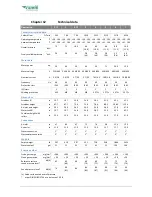
Page 29: ...ding protection MP MP MP MP 3 PTCs 3 PTCs 3 PTCs 3 PTCs Dimensions Scrubber Ø in 19 7 19 7 24 8 24 8 28 3 31 5 43 3 53 1 Scrubber height in 67 7 67 7 75 6 75 6 78 4 88 1 108 2 119 4 Air inlet port height in 29 3 29 3 34 3 34 3 34 8 36 0 37 8 47 8 Water tank Ø in 19 7 19 7 24 8 24 8 28 3 31 5 43 3 43 3 Container height with rollers in 22 4 22 4 22 4 22 4 23 0 23 0 27 9 27 9 Connections Air inlet in...

Page 30: ...y form or processed using electronic systems copied or distributed without the prior written consent of Camfil APC 2014 Camfil APC Manufacturer and service address Camfil Air Pollution Control 3505 South Airport Road Jonesboro AR 72401 Phone 870 933 8048 Toll Free 800 479 6801 Fax 870 933 8381 email filterman camfil com Internet www camfilapc com SERVICE PHONE 870 933 8048 We reserve the right to ...

Reviews: