3
Model 752 and 752A Differential Pressure Transmitters
Section 1
Section 1—Introduction
General
The Model 752 and 752A Differential Pressure Transmitters provide a 4-20
mA or 10-50 mA signal that is proportional to differential pressure and trans-
mits it to remote receiving, control, or readout devices. Sources of differential
pressure include liquid level and specific gravity changes in vessels; flow of
liquids and gases through orifice plates, nozzles or venturis; pressure drop
across filters and static line pressures, etc.
Product Description
The Model 752 and 752A transmitters combine a differential pressure unit
(DPU) with an electronic circuit. The 4-20 mA or 10-50 mA output is compat-
ible with a wide range of electronic receiving, control, and readout equip-
ment. The instrument utilizes miniaturized hybrid electronic circuits and a
molecular-bonded strain gage sensing cantilever beam, actuated directly by
the bellows' travel within the DPU. In many applications, the electrical con-
nections are contained within a junction box, as shown in
However, the junction box is optional.
Differential Pressure Unit
The mechanical actuating device for the Model 752 and 752A transmitters
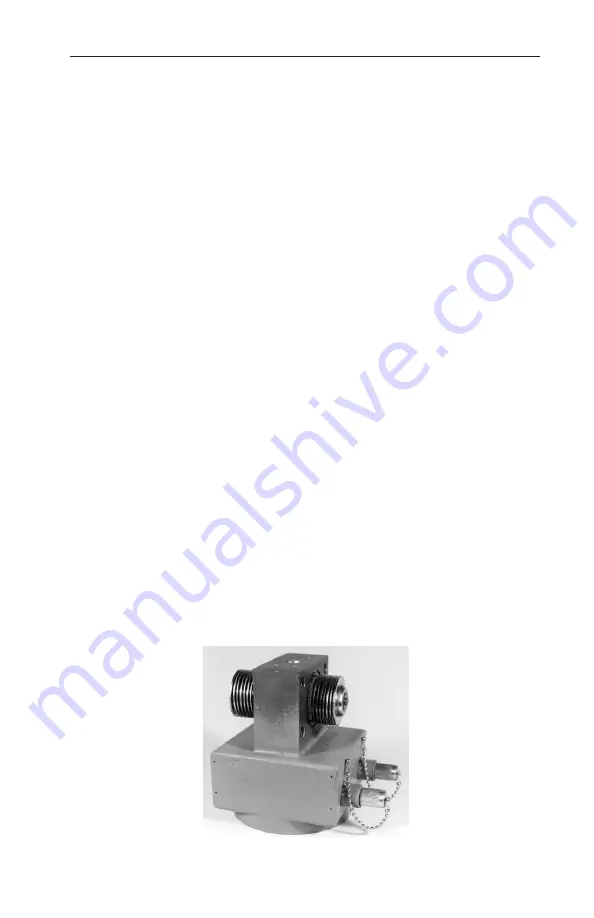
is a dual bellows assembly enclosed by a set of two pressure housings. The
assembly (Figure 1.1 below and
) consists of two internally-
connected bellows, a center block, overrange valves, a temperature compen-
sator, a strain gage assembly, and range springs. The internal volume of the
bellows and center block is filled with a clean, non-corrosive, non-conductive
liquid with a low freezing point, and sealed. The motion-sensing cantilever
beam is also sealed within this environment.
Figure 1.1—Bellows unit assembly (BUA)


