


9
Model 752 and 752A Differential Pressure Transmitters
Section 2
Section 2—Theory of Operation
Basic Components
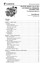
Differential Pressure Unit (DPU)
HP Housing
Valve Stem
HP Bellows
LP Housing
LP Bellows
Figure 2.1—DPU cutaway view
The differential pressure range of the dual-bellows type DPU is determined
by the force required to move the bellows through their normal range of
travel. To provide for various ranges, range springs are incorporated into the
Bellows Unit Assembly (BUA). The range springs, which are available in
various factory assemblies, accurately balance the differential pressure ap-
plied to the DPU.
In operation, the two bellows (which are connected by the valve stem shown
in Figure 2.1) move in proportion to the difference in pressure applied across
the BUA. The linear motion of the bellows is picked up by the tip of the sili-
cone strain gage beam, which is actuated directly by the valve stem connect-
ing the two bellows. If the bellows are subjected to a pressure greater than the
differential pressure range of the DPU, they will move through their normal
range of travel, plus a small additional amount of "overtravel," until the valve
on the stem shaft seals against its valve seat. As the valve closes on the seat, it
"traps" the fill liquid in the bellows, protecting the unit from damage or shift
in calibration.
Since the fill fluid is essentially non-compressible, the bellows are fully sup
-
ported and cannot rupture regardless of the over-pressure (up to the full rated
pressure of the instrument) applied to the unit. Furthermore, since the unit
contains opposed valves, protection against "overrange" in either direction is
provided.
Draining or Venting.
Pressure connections on the top and bottom of the high
and low pressure DPU housings provide a drain when the unit is used in gas
installations, or a vent when the unit is used in liquid installations, when
installed in accordance with standard practices.


