10
for explosionproof units
, cover is unscrewed to gain access to the internal com-
ponents. Note: On some units, a set screw must be loosened with a 1/8-in. allen
wrench before the bezel can be removed. When re-installing cover, tighten cover
securely and inspect lens for cracks or other defects that may affect the explosion-
proof rating.
3-4. Calibration Check
Normally all that is required to put switch into service is to verify that it remains
at factory-set calibration, per the following instructions. (See Warning on pg. 9):
1. Securely mount unit in an appropriately level position and connect DPU to a
standard pressure source, per Model 199 DPU manual.
2. If zero indication is incorrect, remove bezel/lens (cover on explosionproof
units) and reset pointer to zero. Note: For an exact zero setting, hold the
hexagon hub with a wrench and carefully slip the pointer on its hub until it
points to zero graduation. Replace bezel/lens (or cover).
3. To test for reverse travel, connect pressure source to low-pressure (LP) hous-
ing and vent high-pressure (HP) housing. Apply pressures approximately
150% of the differential pressure range. The pointer should move approxi-
mately 5% to 10% below zero.
4. To test for overtravel, connect pressure source to HP housing and vent LP
housing. Apply pressures approximately 150% of differential pressure range.
Pointer should move approximately 5% to 10% above fullscale.
5. Apply 0%, 50% and 100% of full scale pressure. If indication is within
specified limits, instrument calibration is satisfactory and no adjustments are
necessary. If indications are incorrect, perform calibration procedure.
6. Make sure instrument zero indication is correct; otherwise, repeat Step 2.
7. Verify switch setpoints (refer to section 3-7, page 12).
3-5. Pointer Installation and Removal
A. Pointer Installation (See Warning on page 9)
1. Position pointer on movement shaft with pointer set at zero scale. If
necessary, enlarge hub hole using a tapered broach (in toolkit)
(Part No. 0288-1032B).
2. Lightly tap pointer hub with a flat-end tool. Use perpendicular blows to
avoid bending shaft.
3. Check calibration over entire range (see section 3-8.). If unit is correctly
calibrated, secure pointer to
movement shaft by tapping
hub with a hand-set or other
flat-end tool.
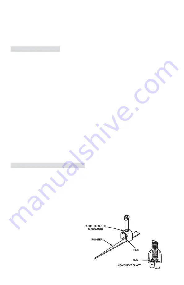
B. Pointer Removal (See Warning
on page 9)
The pointer is removed with
Barton Pointer Puller (Part No.
0163-0005B), which is included
in toolkit (Part No. 0288-1032B).
figure 3-2.
Pointer Puller


