6
D. Torque Tube Assembly
Needle Beaing
Center Plate
Disc
0.200"
Minature
Precision
Shaft
O-Ring Seal
8°
Rotation
Weld
Drive Arm
Valve Stem
Bellows Travel
Valve Stem
Ball Bearing
Torque Tube
Torque Tube
Torque Tube
Lock Nut
Weld
Ball Bearing
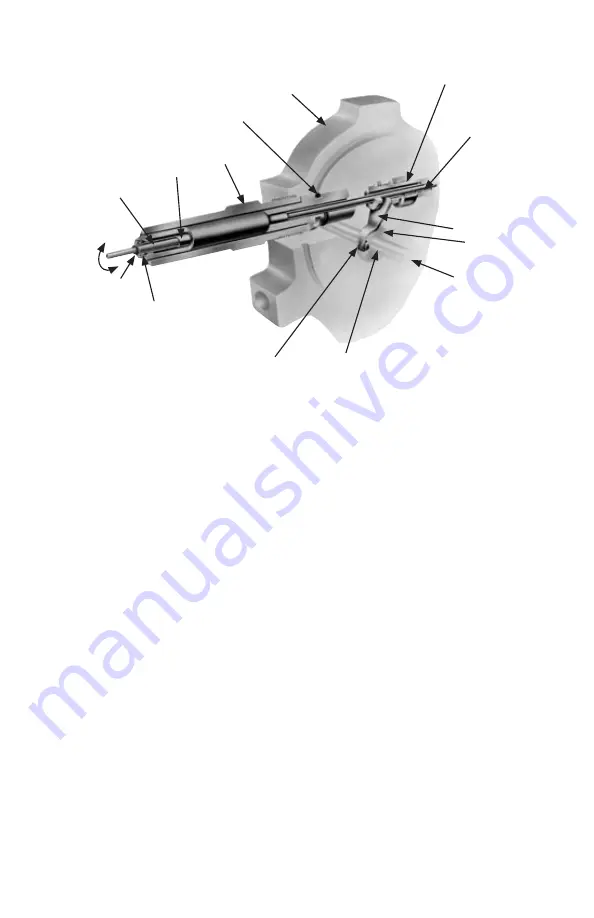
Figure 2-3. Torque Tube Assembly
As illustrated in Figure 2-3, the torque tube assembly consists of a torque
tube, a torque tube shaft, and the supporting members. The outboard end
of the torque tube shaft is attached to the center plate. The torque tube
shaft, located in the center of the torque tube, is welded to the inboard end
of the tube.
Movement of the bellows is transmitted by the drive arm to the torque tube
as a rotary motion. Since the torque tube is attached to the center plate,
the tube must twist when subjected to torque. The torque tube shaft, which
is freely supported within the torque tube at its outer end, but connected
to the torque tube and drive arm at its inner end, rotates through the same
angle as the differential pressure unit.
NOTE: An extended torque tube is used on electronic transmitters and
explosion-proof instruments.
E. Pulsation Dampener
The pulsation dampener (see Figure 2-1) controls the flow of fill-liquid
between the high and low-pressure bellows with an externally adjustable
pulsation dampener needle valve. Restriction of liquid flow reduces the
effects of pulsation. In applications where pulsation is not a problem, the
needle valve is set to the fullopen position.
7


