background image

Стр. 

19

 - Руково

дство 

FA01571-RU

  - 04/2021 - © C

AME S.p.A. - Со

держание э

то

го

 руково

дства може

т быть изменено в любое время без пре

дварит

ельног

о уве

домления. 

- Перево

д оригинальных инструкций

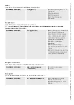
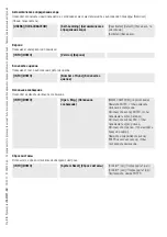
Входные контакты CY

Позволяет закрепить за входными контактами CY одну из доступных функций.

[FUNCTIONS] (ФУНКЦИИ)

[CY input] (Вход CY)

[Deactivated] (Default) (Отключено, по 
умолчанию)
[C1] = Открывание в режиме 
закрывания (фотоэлементы)
[C2] = Закрывание в режиме 
открывания (фотоэлементы)
[C3] = Частичная остановка Только 
при включенной функции [Авт. 
закрывание].
[C4] = Обнаружение препятствия 
(фотоэлементы)
[C7] = Открывание в режиме 
закрывания (чувствительные 
профили)
[C8] = Закрывание в режиме 
открывания (чувствительные 
профили)

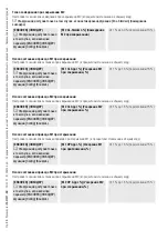
Вход CZ

Позволяет связать с входом CZ одну из доступных функций.

[FUNCTIONS] (ФУНКЦИИ)

[CZ input] (Вход CZ)

[Deactivated] (Отключено)
[C1] = Открывание в режиме 
закрывания (фотоэлементы) (по 
умолчанию)
[C2] = Закрывание в режиме 
открывания (фотоэлементы)
[C3] = Частичная остановка Только 
при включенной функции [Авт. 
закрывание].
[C4] = Обнаружение препятствия 
(фотоэлементы)
[C7] = Открывание в режиме 
закрывания (чувствительные 
профили)
[C8] = Закрывание в режиме 
открывания (чувствительные 
профили)

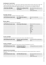
Дожим при закрывании

В конечной точке закрывания ворот приводы выполняют дожим створок в течение нескольких секунд.

[FUNCTIONS] (ФУНКЦИИ)

[Cl. Thrust] (Дожим при 
закрывании)

[Deactivated] (Default) (Отключено, по 
умолчанию)
[Activated] (Включено)

Summary of Contents for ZLJ24

Page 1: ...Quadro comando per motoriduttori a 24 V ZLJ24 ZLJ24Z MANUALE DI INSTALLAZIONE FA01571M04 IT Italiano EN English FR Fran ais RU P...

Page 2: ...ranzia Tutte le operazioni indicate in questo manuale devono essere effettuate esclusivamente da personale esperto e quali cato e nel pieno rispetto delle normative vigenti La predisposizione dei cavi...

Page 3: ...sia visibile in maniera diretta tuttavia lontani dalle parti in movimento Nel caso di comando ad azione mantenuta questo deve essere installato ad un altezza minima di 1 5 m da terra e non deve essere...

Page 4: ...labili ai ri uti solidi urbani e possono essere smaltiti senza alcuna difficolt semplicemente effettuando la raccolta differenziata per il riciclaggio Prima di procedere sempre opportuno veri care le...

Page 5: ...te battenti con display gra co di programmazione e segnalazione e autodiagnosi dei dispositivi di sicurezza 002ZLJ24Z Quadro comando multifunzioni per cancelli a due ante battenti con display gra co d...

Page 6: ...tiera per il collegamento dell antenna 11 Morsettiera per il collegamento del selettore transponder 12 Morsettiera per il collegamento dei necorsa 13 Morsettiera per il collegamento dei dispositivi di...

Page 7: ...ambiente interno invece utilizzare cavi tipo H05VV F conformi alla 60227 IEC 53 IEC Per alimentazioni no a 48 V si possono utilizzare cavi tipo FROR 20 22 II conformi alla EN 50267 2 1 CEI Per il coll...

Page 8: ...oni originali INSTALLAZIONE Preparazione del quadro comando 1 Separare le parti del quadro comando che lo compongono 2 Assemblare le cerniere a pressione 3 Inserire le cerniere nella scatola sul lato...

Page 9: ...i preavviso Istruzioni originali Fissaggio del quadro comando 1 Forare i punti di ssaggio del quadro comando in una zona protetta 2 Fissare la base con viti e tasselli Si consiglia di usare viti a tes...

Page 10: ...izione dei cavi elettrici Eseguire i collegamenti elettrici secondo le disposizioni vigenti Utilizzare dei pressacavi per collegare i dispositivi al quadro comando Uno di questi deve essere destinato...

Page 11: ...eroga 24 V DC quando intervengono le batterie se presenti La somma degli assorbimenti degli accessori connessi non deve superare i 50 W 3 Collegamento elettroserratura 12 V AC max 15 W L N 10 11 TS E...

Page 12: ...rsa 1 Motoriduttore ritardato in apertura 2 Motoriduttore ritardato in chiusura M1 N1 E1 M2 N2 E2 2 FA1FC1FA2FC2 N M M N FC FA F FA FC F Motoriduttore con Encoder 1 Motoriduttore ritardato in apertura...

Page 13: ...one 2 Dispositivo di comando contatto NO Funzione SOLO APRE Con funzione AZIONE MANTENUTA attiva obbligatorio il collegamento del dispositivo di comando in APERTURA 3 Dispositivo di comando contatto N...

Page 14: ...omazione 10 11 TS E ES 1 2 3 3P 4 5 7 CX CY CZ Dispositivi di sicurezza In fase di programmazione con gurare il tipo di azione che deve essere svolta dal dispositivo collegato all ingresso Collegare i...

Page 15: ...i originali Fotocellule DIR DELTA S Collegamento standard Fotocellule DIR DELTA S Collegamento con test di sicurezza Vedi funzione Test sicurezze 10 11 TS E ES 1 2 3 3P 4 5 7 CX CY CZ 10 2 TX C NC TX...

Page 16: ...e con la messa in funzione L operazione deve essere effettuata solo da personale esperto e quali cato Controllare che l area di manovra sia libera da qualsiasi ostacolo Dare tensione e procedere con l...

Page 17: ...ermo se i dispositivi di sicurezza rilevano un ostacolo La funzione ha effetto con cancello chiuso cancello aperto o dopo uno stop totale FUNZIONI Ril Ostacolo Disattivato Default Attivato Test sicure...

Page 18: ...vato C1 Riapertura durante la chiusura Fotocellule C2 Richiusura durante l apertura Fotocellule C3 Stop parziale Default Solo con Ch automatica attivata C4 Attesa ostacolo Fotocellule C7 Riapertura du...

Page 19: ...ura A necorsa in chiusura l automazione esegue una spinta in battuta delle ante per alcuni secondi FUNZIONI Spinta Ch Disattivato Default Attivato Serratura Permette di associare lo sblocco dell elett...

Page 20: ...e Ap parziale nel menu REGOLA TEMPI Pedonale Default Lampada supplementare Permette di scegliere la modalit di funzionamento del dispositivo di illuminazione collegato all uscita FUNZIONI Lampada E La...

Page 21: ...zio sufficiente a liberare l ostacolo Con funzione disattivata avviene l inversione di marcia no al raggiungimento del necorsa FUNZIONI Libera ostacolo Disattivato Default Attivato Numero motori Impos...

Page 22: ...elle ante durante le fasi di rallentamento Fcap RallCh inversione della marcia durante la manovra e arresto delle ante durante il rallentamento in chiusura IMP CORSA Sen Amperom Disattivato Default At...

Page 23: ...Da 1 a 60 Default 10 Punto di rallentamento in chiusura di M1 Imposta il punto di inizio del rallentamento in chiusura di M1 percentuale della corsa totale Questa funzione compare solo se attiva la fu...

Page 24: ...della corsa totale ENCODER Questa funzione compare solo se attivo il parametro ENCODER dalla funzione Con g M1 Acc AP Da 1 a 15 Default 15 Punto di accostamento in apertura di M2 Imposta il punto di i...

Page 25: ...fault 90 secondi Ritardo in apertura di M1 Regola il ritardo con il quale M1 deve iniziare la manovra di apertura rispetto a M2 REGOLA TEMPI Rit Ap M1 da 0 a 10 secondi Default 2 secondi Ritardo in ch...

Page 26: ...TI Nuovo Utente Disattivato 2 7 Comando passo passo o sequenziale Apre B1 B2 2 3P Apertura pedonale o parziale 1 Scegliere la funzione che si vuole assegnare all utente 2 Premere ENTER per confermare...

Page 27: ...le caricare solo gli utenti UTENTI Carica Memoria Confermi no Confermi si Decodi ca radio Permette di scegliere il tipo di codi ca radio dei trasmettitori abilitati a comandare l automazione Scegliend...

Page 28: ...Tenere premuto ENTER per qualche secondo per confermare Reset sistema Per il ripristino delle impostazioni di fabbrica INFO Reset Sistema Confermi no Confermi si Premere ENTER per confermare Test moto...

Page 29: ...senza obbligo di preavviso Istruzioni originali Cambia password Permette di modi care la password Password Cambia PSW Confermi no Confermi si Usare le frecce per selezionare un numero Premere ENTER p...

Page 30: ...ato L Encoder rotto Errore L Encoder scollegato L Encoder rotto Test Sicurezze ERRORE Le fotocellule non sono collegate o con gurate correttamente Fine corsa ERRORE Malfunzionamento sui contatti di ne...

Page 31: ...sono da ritenersi suscettibili di modi ca in qualsiasi momento senza obbligo di preavviso Istruzioni originali OPERAZIONI FINALI Prima di chiudere il coperchio veri care che l ingresso dei cavi sia s...

Page 32: ...I contenuti del manuale sono da ritenersi suscettibili di modi ca in qualsiasi momento senza obbligo di preavviso Istruzioni originali CAME S p A Via Martiri della Libert 15 31030 Dosson di Casier Tre...

Page 33: ...Control panel for 24 V gearmotors ZLJ24 ZLJ24Z INSTALLATION MANUAL FA01571 EN EN English...

Page 34: ...ndicated in this manual must be carried out exclusively by skilled and quali ed personnel and in full compliance with the regulations in force The device must be installed wired connected and tested a...

Page 35: ...ectly visible but far away from moving parts In the case of a hold to run control this must be installed at a minimum height of 1 5 m from the ground and must not be accessible to the public If not al...

Page 36: ...ING The packaging materials cardboard plastic etc can be disposed of easily as solid urban waste separated for recycling Before dismantling and disposing of the product please always check the local l...

Page 37: ...ates with two leaves Graphic programming display and signalling and self diagnostics using safety devices 002ZLJ24Z Multifunction control panel for swing gates with two leaves Graphic programming disp...

Page 38: ...for connecting the antenna 11 Terminal board for connecting the transponder selector switch 12 Terminal board for connecting the limit switches 13 Terminal board for connecting control and safety dev...

Page 39: ...H05RN F cables compliant with 60245 IEC 57 IEC when operating indoors use H05VV F cables compliant with 60227 IEC 53 IEC For power supplies up to 48 V you can use FROR 20 22 II cables compliant with...

Page 40: ...inal instructions INSTALLATION Preparing the control panel 1 Separate the parts of the control panel 2 Assemble the pressure hinges 3 Insert the hinges into the box either on the left or the right and...

Page 41: ...anslation of the original instructions Fastening the control panel 1 Drill the xing points in the control panel in a protected area 2 Fasten the base using screws and plugs Use Phillips round head scr...

Page 42: ...Preparing the electrical cables Connect all wires and cables in compliance with the law Use cable glands to connect the devices to the control panel One of these must be used exclusively for the powe...

Page 43: ...en the batteries start operating if they are installed The sum of the power draw for the connected accessories must not exceed 50 W 3 Connection for the 12 V AC electric lock 15 W max L N 10 11 TS E E...

Page 44: ...ch 1 Gearmotor delayed while opening 2 Gearmotor delayed while closing M1 N1 E1 M2 N2 E2 2 FA1FC1FA2FC2 N M M N FC FA F FA FC F Gear motor with encoder 1 Gearmotor delayed while opening 2 Gearmotor de...

Page 45: ...Control device NO contact OPEN ONLY function When the HOLD TO RUN function is active the control device must be connected during OPENING 3 Control device NO contact PARTIAL OPENING function 4 Control...

Page 46: ...perator status 10 11 TS E ES 1 2 3 3P 4 5 7 CX CY CZ Safety devices During programming con gure the type of action that must be performed by the device connected to the input Connect the safety device...

Page 47: ...tions DIR DELTA S photocells Standard connection DIR DELTA S photocells Connection with safety test See Safety devices test function 10 11 TS E ES 1 2 3 3P 4 5 7 CX CY CZ 10 2 TX C NC TX 2 RX TX 10 11...

Page 48: ...have been made proceed with commissioning Only skilled and quali ed staff may perform this operation Make sure that there are no obstacles in the way Power up and proceed with the operations indicated...

Page 49: ...ate remains idle if the safety devices detect an obstacle The function is active when the gate is closed open or after a complete stop FUNCTIONS Obstruction det Deactivated Default Activated Safety de...

Page 50: ...activated C1 Reopen while closing photocells C2 Reclose while opening Photocells C3 Partial stop Default Only with Automatic close activated C4 Obstacle standby Photocells C7 Reopen while closing sens...

Page 51: ...hrust When the leaves reach the closing limit switch the operator performs a closing thrust for a few seconds FUNCTIONS Cl thrust Deactivated Default Activated Lock Associate the electric lock release...

Page 52: ...is set with the Part open function in the SET TIME menu Pedestrian Default Additional light Choose the operating mode of the lighting device connected to the output FUNCTIONS Light E Flashing light D...

Page 53: ...space sufficient to clear the obstacle If this function is deactivated the motion is inverted until the limit switch is reached FUNCTIONS Remove obstacle Deactivated Default Activated Number of motor...

Page 54: ...eaves during slowdown Op LS Cl Slow invert travel during a manoeuvre and stop the leaves during closing slowdown SET TRAVEL Amperom sens Deactivated Default Activated Travel amperometrics Adjust the a...

Page 55: ...to 60 Default 10 M1 closing slowdown point Set the closing slowdown starting point for M1 percentage of the total travel This function appears only if the Enc Slow function is active ENCODER This func...

Page 56: ...f the total travel ENCODER This function appears only if the ENCODER parameter is activated from the Con g function M1 Appr OP From 1 to 15 Default 15 Opening approach point for M2 Set the opening app...

Page 57: ...me from 10 to 150 seconds Default 90 seconds M1 opening delay Adjust the delay in starting the opening manoeuvre for M1 with respect to M2 SET TIME Open delay M1 from 0 to 10 seconds Default 2 seconds...

Page 58: ...ping in L20180423 USERS New user Deactivated 2 7 Step by step or sequential control Open B1 B2 2 3P Pedestrian or partial opening 1 Choose the function to be assigned to the user 2 Press ENTER to con...

Page 59: ...ly the users can be loaded USERS Load memory Con rm No Con rm Yes Radio decoding Choose the type of radio coding for the transmitters enabled to control the operator If you choose the type of radio co...

Page 60: ...a number Press and hold ENTER for a few seconds to con rm Resetting the system Restore factory settings INFO System reset Con rm No Con rm Yes Press ENTER to con rm Motor test Check the gate leaves op...

Page 61: ...me and without notice Translation of the original instructions Change password Change the password Password Change PSW Con rm No Con rm Yes Use the arrows to select a number Press ENTER to con rm Ente...

Page 62: ...he Encoder is broken Error The Encoder is disconnected The Encoder is broken Safety test ERROR The photocells are not correctly connected or con gured Limit switch ERROR Malfunctioning limit switch co...

Page 63: ...he contents of this manual may be changed at any time and without notice Translation of the original instructions FINAL OPERATIONS Before closing up the casing check that the cable inlets are sealed t...

Page 64: ...AME S p A The contents of this manual may be changed at any time and without notice Translation of the original instructions CAME S p A Via Martiri della Libert 15 31030 Dosson di Casier Treviso Italy...

Page 65: ...Armoire de commande pour motor ducteurs 24 V ZLJ24 ZLJ24Z MANUEL D INSTALLATION FA01571 FR FR Fran ais...

Page 66: ...its non originaux ce qui implique galement l annulation de la garantie Toutes les op rations indiqu es dans ce manuel ne doivent tre ex cut es que par du personnel quali et dans le plein respect des n...

Page 67: ...t directement visible mais l cart des parties en mouvement Toute commande action maintenue doit tre install e une hauteur minimum de 1 5 m par rapport au sol et doit tre inaccessible au public d faut...

Page 68: ...urbains solides et peuvent tre limin s sans aucune difficult en proc dant tout simplement la collecte diff renci e pour le recyclage Avant d effectuer ces op rations il est toujours recommand de v ri...

Page 69: ...x vantaux avec afficheur de programmation et de signalisation et autodiagnostic des dispositifs de s curit 002ZLJ24Z Armoire de commande multifonctions pour portails battants deux vantaux avec affiche...

Page 70: ...r quence en chable AF 10 Bornier de connexion de l antenne 11 Bornier de connexion du s lecteur transpondeur 12 Bornier de connexion des but es de n de course 13 Bornier de connexion des dispositifs d...

Page 71: ...a norme 60245 IEC 57 IEC en int rieur utiliser par contre des c bles H05VV F conformes la norme 60227 IEC 53 IEC Pour les alimentations jusqu 48 V il est possible d utiliser des c bles FROR 20 22 II c...

Page 72: ...nales INSTALLATION Pr paration de l armoire de commande 1 S parer les parties de l armoire de commande qui la composent 2 Assembler les charni res pression 3 Introduire les charni res dans le bo tier...

Page 73: ...tions originales Fixation de l armoire de commande 1 Percer les points de xation de l armoire de commande dans une zone prot g e 2 Fixer la base l aide de vis et de chevilles Il est conseill d viter d...

Page 74: ...ion des c bles lectriques Effectuer les branchements lectriques selon les dispositions en vigueur Utiliser des passe c bles pour connecter les dispositifs l armoire de commande Un de ces passe c bles...

Page 75: ...d intervention des ventuelles batteries La somme des absorptions des accessoires connect s ne doit pas d passer 50 W 3 Connexion serrure de verrouillage lectrique 12 V AC max 15 W L N 10 11 TS E ES 1...

Page 76: ...rd durant la phase d ouverture 2 Motor ducteur retard durant la phase de fermeture M1 N1 E1 M2 N2 E2 2 FA1FC1FA2FC2 N M M N FC FA F FA FC F Motor ducteur avec Encodeur 1 Motor ducteur retard durant la...

Page 77: ...mmande contact NO Fonction OUVERTURE SEULEMENT Avec fonction ACTION MAINTENUE activ e la connexion du dispositif de commande en OUVERTURE est obligatoire 3 Dispositif de commande contact NO Fonction O...

Page 78: ...e l tat de l automatisme 10 11 TS E ES 1 2 3 3P 4 5 7 CX CY CZ Dispositifs de s curit Pendant la programmation con gurer le type d action que le dispositif connect l entr e doit effectuer Connecter le...

Page 79: ...tions originales Photocellules DIR DELTA S Connexion standard Photocellules DIR DELTA S Connexion avec test de s curit Voir fonction Test s curit 10 11 TS E ES 1 2 3 3P 4 5 7 CX CY CZ 10 2 TX C NC TX...

Page 80: ...arche L op ration ne doit tre effectu e que par du personnel quali et sp cialis S assurer que la zone de man uvre ne pr sente aucun obstacle Mettre sous tension et ex cuter les op rations suivantes Ty...

Page 81: ...sitifs de s curit d tectent un obstacle La fonction est activ e avec portail ferm portail ouvert ou apr s un arr t total FONCTIONS D t Obstacle D sactiv e par d faut Activ e Test s curit Active le con...

Page 82: ...e durant la fermeture Photocellules C2 Refermeture durant l ouverture Photocellules C3 Arr t partiel par d faut Uniquement avec Ferm automatique activ e C4 Attente obstacle Photocellules C7 R ouvertur...

Page 83: ...ure l automatisme pousse les vantaux jusqu la but e pendant quelques secondes FONCTIONS Pouss e Ferm D sactiv e par d faut Activ e Serrure Permet d associer le d blocage du dispositif de verrouillage...

Page 84: ...la fonction Ouv partielle dans le menu R GLAGE TEMPS Pi tonne par d faut Lampe suppl mentaire Permet de choisir le mode de fonctionnement de l appareil d clairage connect la sortie FONCTIONS Lampe E C...

Page 85: ...suffise pour lib rer l obstacle Lorsque cette fonction est d sactiv e il y a inversion du sens de marche jusqu la but e de n de course FONCTIONS Mode sans obstacle D sactiv e par d faut Activ e Nombre...

Page 86: ...durant les phases de ralentissement FcOuv RalFer inversion de la marche durant la man uvre et arr t des vantaux durant le ralentissement INST COURSE Cap Amp rom D sactiv e par d faut Activ e Amp rom t...

Page 87: ...0 Point de ralentissement en fermeture de M1 Con gure le point de ralentissement initial la fermeture de M1 pourcentage de la course totale Cette fonction n appara t qu en cas d activation de la fonct...

Page 88: ...ENCODEUR Cette fonction n appara t qu en cas d activation du param tre ENCODEUR par la fonction Con g M1 Rapp OUV De 1 15 par d faut 15 Point de rapprochement en ouverture de M2 Con gure le point init...

Page 89: ...ouverture de M1 R gle le d lai de retard avec lequel M1 doit commencer la man uvre d ouverture par rapport M2 R GLAGE TEMPS Ret Ouv M1 de 0 10 secondes par d faut 2 secondes Retard la fermeture de M2...

Page 90: ...eur D sactiv e 2 7 Commande pas pas ou s quentielle Ouverture B1 B2 2 3P Ouverture pi tonne ou partielle 1 Choisir la fonction attribuer l utilisateur 2 Appuyer sur ENTER pour con rmer Le syst me dema...

Page 91: ...version sinon il sera seulement possible de charger les utilisateurs UTILISATEURS T l charger M moire Con rmer non Con rmer oui D codage radio Permet de choisir le type de codage radio des metteurs p...

Page 92: ...onc ENTER pendant quelques secondes pour con rmer R initialiser syst me Pour la r initialisation des con gurations par d faut INFOS R Z Syst me Con rmer non Con rmer oui Appuyer sur ENTER pour con rme...

Page 93: ...ction des instructions originales Modi er mot de passe Permet de modi er le mot de passe Mot de passe Modi er MdP Con rmer non Con rmer oui Utiliser les ches pour s lectionner un num ro Appuyer sur EN...

Page 94: ...reur L encodeur est d connect L encodeur est cass Test S curit s ERREUR Les photocellules ne sont pas connect es ou con gur es correctement Fin de course ERREUR Mauvais fonctionnement sur les contacts...

Page 95: ...tible de subir des modi cations tout moment et sans aucun pr avis Traduction des instructions originales OP RATIONS FINALES Avant de fermer le couvercle s assurer que l entr e des c bles est bien scel...

Page 96: ...contenu de ce manuel est susceptible de subir des modi cations tout moment et sans aucun pr avis Traduction des instructions originales CAME S p A Via Martiri della Libert 15 31030 Dosson di Casier Tr...

Page 97: ...24 ZLJ24 ZLJ24Z FA01571 RU RU...

Page 98: ...2 FA01571 RU 04 2021 CAME S p A 2006 42 CE 2006 42 CE 2006 42 CE CAME www came com III...

Page 99: ...3 FA01571 RU 04 2021 CAME S p A 1 5 2006 42 CE...

Page 100: ...4 FA01571 RU 04 2021 CAME S p A CAME S p A UNI EN ISO 14001...

Page 101: ...5 FA01571 RU 04 2021 CAME S p A 002ZLJ24 002ZLJ24Z ZLJ24 24 24 10 500 C 120 RAL 7040 C 20 55 150 IP 54 II ZLJ24 3 15 A F 630 mA F 2 A F...

Page 102: ...4 5 6 7 8 R700 9 AF 10 11 12 13 14 15 16 17 18 19 20 21 22 RSE 23 CRP L N E E 10 11 TS E ES 1 2 3 4 5 CX CY CZ 7 2 FA2 FC2 FA1 FC1 M1 M2 N1 N2 ENC1 ENC2 L2T L1T L2T L1T 24 12 0 24 12 0 B1 B2 S1 GND 2...

Page 103: ...3G x 1 5 3G x 2 5 24 2 x 0 5 2 x 0 5 TX 2 x 0 5 2 x 0 5 RX 4 x 0 5 4 x 0 5 12 2 x 1 2 x 1 5 n x 0 5 n x 0 5 n 230 H05RN F 60245 IEC 57 IEC H05VV F 60227 IEC 53 IEC 48 FROR 20 22 II EN 50267 2 1 CEI RG...

Page 104: ...8 FA01571 RU 04 2021 CAME S p A 1 2 3 4 20...

Page 105: ...9 FA01571 RU 04 2021 CAME S p A 1 2 6 3 295 215...

Page 106: ...10 FA01571 RU 04 2021 CAME S p A L N E E 10 11 TS E ES 1 2 3 4 5 CX CY CZ 7 2 FA2 FC2 FA1 FC1 M1 M2 N1 N2 ENC1 ENC2 L2T L1T L2T L1T 24 12 0 24 12 0 B1 B2 S1 GND 26 0V 17 0 230V 26 0V 17 0 230V B A GND...

Page 107: ...11 FA01571 RU 04 2021 CAME S p A 1 120 230 50 60 2 24 24 50 3 12 15 L N 10 11 TS E ES 1 2 3 3P 4 5 7 CX CY CZ 10 11 24 50 10 E 24 25 10 5 24 3 1 2 M1 N1 E1 M2 N2 E2 N M M N...

Page 108: ...04 2021 CAME S p A 1 2 M1 N1 E1 M2 N2 E2 2 FA1FC1FA2FC2 N M M N FC FA F FA FC F 1 2 M1 N1 E1 M2 N2 E2 N E M M N E AMICO AXO FROG J MYTO ATS M1 N1 E1 E M2 N2 E2 E N M M N E E a c b a b c F4000 FAST FE...

Page 109: ...13 FA01571 RU 04 2021 CAME S p A 1 2 3 4 5 2 7 6 7 8 RG58 10 11 TS E ES 1 2 3 3P 4 5 7 CX CY CZ S1 GND...

Page 110: ...2021 CAME S p A 1 2 3 10 11 TS E ES 1 2 3 3P 4 5 7 CX CY CZ CX CY CZ NC CX CY CZ DELTA DELTA 10 11 NO C NC 10 11 RX TX 10 11 ES TS 1 2 3 3P 4 5 7 CX CY CZ 10 11 TS E ES 1 2 3 3P 4 5 7 CX CY CZ 10 11 N...

Page 111: ...A DIR DELTA S DIR DELTA S 10 11 TS E ES 1 2 3 3P 4 5 7 CX CY CZ 10 2 TX C NC TX 2 RX TX 10 11 TS E ES 1 2 3 3P 4 5 7 CX CY CZ 10 2 TX C NC TX 2 RX TX DFWN 10 11 TS E ES 1 2 3 3P 4 5 7 CX CY CZ 3 3P 4...

Page 112: ...16 FA01571 RU 04 2021 CAME S p A 1 2 3 1 ESC ESC 2 3 ENTER ENTER ESC LANGUAGE Italiano Default English Fran ais Deutsch Espa ol Portugu s euro Portugu s bras...

Page 113: ...lt 2 3 2 4 FUNCTIONS Maintained Act Deactivated Default Activated When closing FUNCTIONS Obstruction Det Deactivated Default Activated FUNCTIONS Safety devices test Deactivated Default CX CY CZ CX CY...

Page 114: ...571 RU 04 2021 CAME S p A Jolt stop T FUNCTIONS Jolt stop Deactivated Default Close Open Open Close FUNCTIONS Total Stop Deactivated Activated Default CX CX FUNCTIONS CX Input CX Deactivated C1 C2 C3...

Page 115: ...FA01571 RU 04 2021 CAME S p A CY CY FUNCTIONS CY input CY Deactivated Default C1 C2 C3 C4 C7 C8 CZ CZ FUNCTIONS CZ input CZ Deactivated C1 C2 C3 C4 C7 C8 FUNCTIONS Cl Thrust Deactivated Default Activa...

Page 116: ...ock Deactivated Default Close Open Open Close Slwdwn OpLs ClSloDwn Slwdwn time FUNCTIONS Con g Slwdwn OpLs ClSloDwn ENCODER Time LS Limit switch FUNCTIONS Limit switch N C N O 2 7 2 7 FUNCTIONS 2 7 Co...

Page 117: ...artial open SET TIMES Pedestrian Default FUNCTIONS Light E Flashing light Default Courtesy 5 Cycle B1 B2 FUNCTIONS Output B1 B2 B1 B2 Monostable Button Bistable Switch CRP FUNCTIONS CRP address CRP 1...

Page 118: ...vated Default Activated SET TRAVEL No of Motors M1 M2 M2 SET TRAVEL Motor Type FROG F4024E FROG J FROG FL AMICO MYTO AXO ATS FAST FERNI ATI SET TRAVEL Maneuver speed 20 100 100 SET TRAVEL Slowing down...

Page 119: ...SloDwn SET TRAVEL Amperon Sens Deactivated Default Activated Amperon Sens SET TRAVEL Amperom Travel OpLs ClSloDwn Slwdwn Con g SET TRAVEL Slwdwn time 0 30 20 ENCODER ENCODER Con g Sensitivity Activate...

Page 120: ...ensitivity Enc Slwdwn ENCODER ENCODER Con g Slodwn Sens 1 1 Enc Slwdwn ENCODER ENCODER Con g M1 Op Slwdwn 1 1 60 10 1 1 Enc Slwdwn ENCODER ENCODER Con g M1 CL Slwdwn 1 1 60 10 2 2 Enc Slwdwn ENCODER E...

Page 121: ...Slwdwn ENCODER ENCODER Con g M2 CL Slwdwn 2 1 60 10 M1 1 ENCODER ENCODER Con g M1 CL Appr 1 1 15 15 M2 2 ENCODER ENCODER Con g M2 CL Appr 2 1 15 15 1 1 ENCODER ENCODER Con g M1 OP Appr 1 1 15 15 M2 2...

Page 122: ...Con g Calibrate Gate Swing Con rm no Con rm yes SET TIMES A C T 0 300 10 SET TIMES Pedestrian ACT 0 300 10 SET TIMES Working Time 10 150 90 M1 1 2 SET TIMES Open Delay M1 M1 0 10 2 M2 2 1 SET TIMES Cl...

Page 123: ...RU 04 2021 CAME S p A SET TIMES Lock time 1 5 2 SET TIMES Jolt stop T 1 10 1 250 AF R700 R800 docs came com L20180423 USERS New User Deactivated 2 7 Opens B1 B2 2 3P 1 2 ENTER 3 USERS Edit name USERS...

Page 124: ...ciated Funct 2 7 Opens B1 B2 2 3P USERS Remove Usr USERS Delete all Usr Con rm no Con rm yes USERS Backup data Con rm no Con rm yes ENTER USERS Restore backup Con rm no Con rm yes TW USERS Radio decod...

Page 125: ...1 RU 04 2021 CAME S p A New User USERS Self Learning Deactivated Default Activated INFO Version INFO Number of Runs INFO Open Msg WWW CAME COM ENTER ENTER ESC ENTER INFO System Reset Con rm no Con rm...

Page 126: ...30 FA01571 RU 04 2021 CAME S p A MOT TEST M1 M2 M1 M2 4 Password Con rm no Con rm yes ENTER Password Change password Con rm no Con rm yes ENTER Password Remove password Con rm no Con rm yes...

Page 127: ...31 FA01571 RU 04 2021 CAME S p A 1 2 C1 C3 C4 C7...

Page 128: ...32 FA01571 RU 04 2021 CAME S p A CAME S p A Via Martiri della Libert 15 31030 Treviso Italy 39 0422 4940 39 0422 4941...

Reviews: