5(0
5%0
5(0
5(0
:$9(
RBM 84
RBM84 -
Hardware and connections
15
Pa
g
e
1515
-
M
an
u
al
c
od
e:
FA
0
0
18
9
M
0
4
FA
0
0
18
9
M
0
4
ve
r.
1
10
/2
0
1
5
© C
A
M
E
s.p.a. - T
h
e d
ata a
n
d i
n
fo
rm
ati
on p
rovi
d
ed
in
th
is
m
an
u
al
a
re s
u
b
je
ct to c
h
an
g
e at a
ny ti
m
e w
ith
ou
t p
ri
or n
oti
ce
by C
A
M
E S
.p.a.
to successive
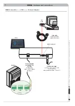
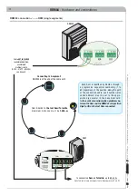
Rem or Turnstile
*
(
INPUT
OR
OUTPUT
CAN
BE
CONNECTED
TO
TERMINAL
BLOCK
1
OR
2)
* the sum of the Rem and/or Turnstiles
that are serial connected along the
segment A+B must be at most 60 units
to successive Rem or Turnstile
*
(
INPUT
OR
OUTPUT
CAN
BE
CONNECTED
TO
TERMINAL
BLOCK
1
OR
2)
Segment A*
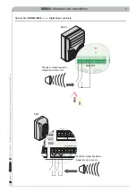
Two SEGMENT connection: RBM84 can be
located in any position along the cable route
from the fi rst to the last Rem/Turnstile,
maximum distance must be
1000 m
Segment B
Each Rem is identifi ed by Rbm84 through
progressive sequential numbering (1 to 60)
regardless of the position along the path of
the connection cable; such number (also
called address) must be set on the appro-
priate dip selector in the base Rem card.
RBM84 connection <----> REM (two segments)
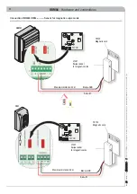
Cable
NOT INCLUDED
recommended type:
unshielded
multipair cable
(CAT 5 - U/UTP - AWG24)
see Annex A
Cable
NOT INCLUDED
recommended type:
unshielded
multipair cable
(CAT 5 - U/UTP - AWG24)
see Annex A


