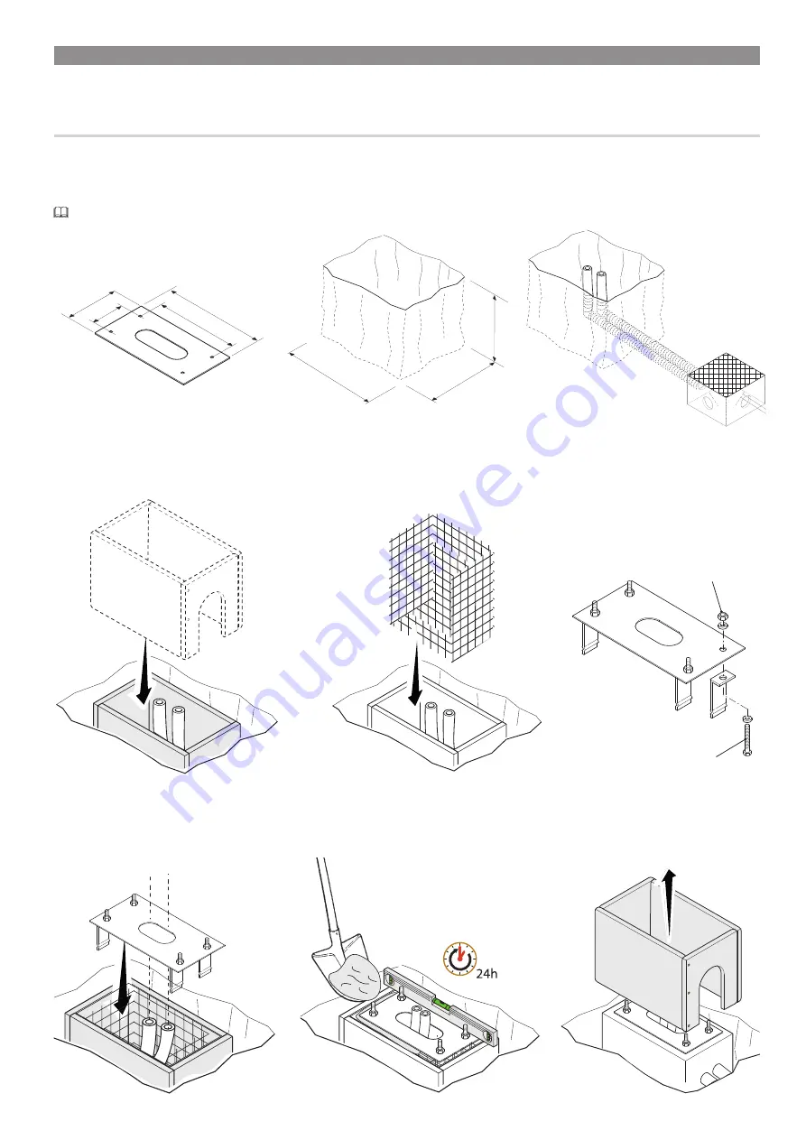
400
700
500
460
380
240
140
M12 UNI5588
M12x40 UNI 5739
p.
7
- M
anu
al
FA0
158
1-
EN
-
03
/2
02
1 - © C
AM
E Ö
ZA
K. - T
ra
ns
la
tio
n o
f t
he o
rig
in
al i
ns
tru
ct
io
ns - T
he c
on
te
nt
s o
f t
hi
s m
anu
al m
ay c
ha
ng
e, a
t a
ny t
ime
, a
nd wi
th
ou
t n
ot
ic
e.
INSTALLING
⚠
The following illustrations are mere examples. Consider that the space available where to fit the barrier and accessories will vary
depending on the area where it is installed. It is up to the installer to find the most suitable solution.
SETTING UP THE ANCHORING PLATE
⚠
If the flooring does not allow for a sturdy fastening of the entry unit, you will have to set up a cement slab.
Dig a hole for the foundation frame.
Set up the corrugated tubes needed for the wiring coming out of the junction pit.
The number of tubes depends on the type of system and the accessories you are going to fit. Set up a 230 V power-supply cable.
Place the plate over the iron cage.
Fill the foundation frame with concrete. The base must be perfectly level with the bolts which are entirely above surface.
Wait at least 24 hrs for the concrete to solidify.
Remove the foundation frame.
Set up a foundation frame that is larger than the anchoring plate and sink it into the dug hole.
Fit an iron cage into the foundation frame to reinforce the concrete.
Assemble the four anchoring braces to the anchoring plate.
Summary of Contents for G6000T
Page 2: ...2 1...


