background image

—

—

p. 

1111

 - M

an

u

al

 c

od

e: 

F

A

0

1

2

8

3

-E

N

FA

0

1

2

8

3

-E

N

 v.


11

- 1

1/

2

0

18 - © C

am

e S

.p.

A

. - T

h

e m

an

u

al

's c

onte

nts m

ay b

e e

d

ite

d at a

ny ti

m

e w

ith

ou

t n

oti

ce

.

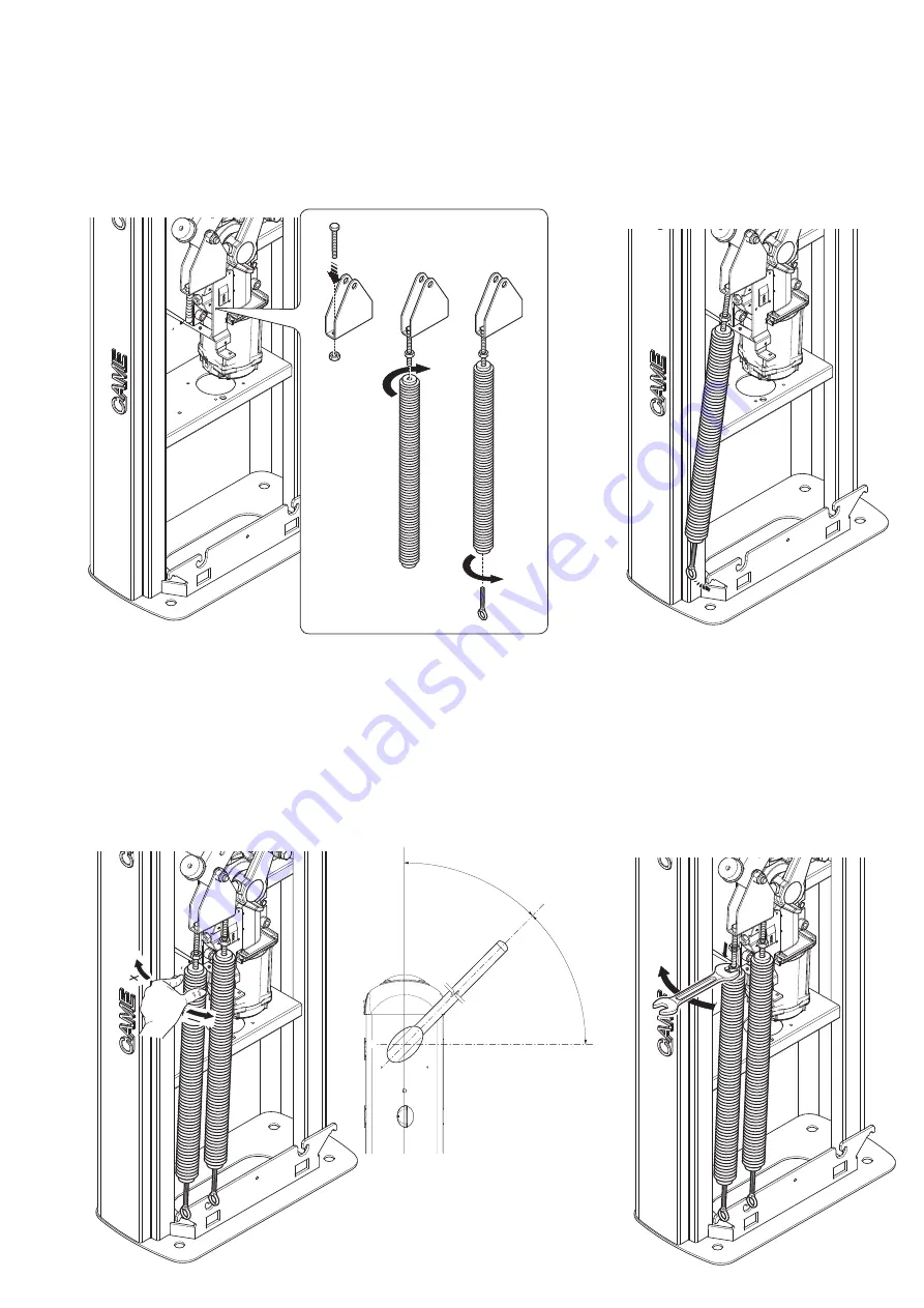
Release the gearmotor and manually turn the spring to increase or decrease tautness. The spring should stabilize at 45°.

Fasten the counter nut and lock the gearmotor again.

 Check the proper working state of the spring. 

With the boom raised vertically the spring is not taut.
With the boom lowered horizontally the spring is taut.

Release the gearmotor and position the boom vertically. Lock the gearmotor again.
Install the spring into the barrier in the following way:
- fit a UNI5739 M12x70 screw into the attachment bracket and tighten the UNI5588 M12 nut to the screw 

.

- tighten the screw into the spring


;

- tighten 

the eyelet tie rod below the spring


.

Hook the tie rod to the anchoring bracket. 
Perform the same procedure for a possible second spring.

Summary of Contents for G2080EZC

Page 1: ...Automatic barriers GARD 8 series G2080EZC INSTALLATION AND OPERATION English FA01283 EN...

Page 2: ...tive regulation grounding system The manufacturer declines any liability for using non original products which would result in warranty loss All maintained action commands must be tted in places from...

Page 3: ...high rates of vehicle traffic Any installation and or use other than that specified in this manual is forbidden Limits to use Type G2080EZC Maximum clearance width of the passage m 7 60 REFERENCE REGU...

Page 4: ...iption of parts 1 Dome 2 Motor shaft plate 3 Mid plate 4 Boom attachment cover 5 Protective casing shear proof 6 Cabinet 7 Casing for key switch and digital selectors 8 Control panel 9 Lever arm 10 Bo...

Page 5: ...trol and safety devices and accessories ensures easy installation and system maintenance Preliminary checks Before beginning do the following make sure the plate is anchored to a solid spot make sure...

Page 6: ...try unit you will have to set up a cement slab Dig a hole for the foundation frame Set up the corrugated tubes needed for making the connections coming out of the junction pit The number of tubes depe...

Page 7: ...rce the concrete Assemble the four anchoring brackets to the anchoring plate Place the plate over the iron cage Fill the foundation frame with concrete The base must be perfectly level with the bolts...

Page 8: ...motor arm headless screw remove the spring attaching bracket and the lever arm transmission rod turn the lever arm by 90 fasten the spring attaching bracket to the transmission rod on the part opposit...

Page 9: ...ap Motor shaft plate Mid plate Boom attachment cover Boom endcap Installing the barrier The cabinet should be installed with the inspection hatch on the most accessible side to make any adjusting easi...

Page 10: ...or 001G02808 swing rest 001G02808 For passage width clearances of up to max 7 m 001G02807 MUST be used with passage width clearances of over 7 m 001G0465 001G02808 Cannot be used together A Spring 001...

Page 11: ...the spring With the boom raised vertically the spring is not taut With the boom lowered horizontally the spring is taut Release the gearmotor and position the boom vertically Lock the gearmotor again...

Page 12: ...rial 31 SPLIT ROUND CABLE ASSEMBLY mod 0431177081 to the inside of the control panel and onto the control warning and safety device cables Description of parts 1 Transformer 2 Power supply terminals 3...

Page 13: ...N v 1 1 11 2018 Came S p A The manual s contents may be edited at any time without notice Power supply 230 V AC 50 60 Hz Terminals for powering up accessories a 24 V AC normally a 24 V DC when the eme...

Page 14: ...rd Contact rated for 24 V AC 32 W max If flashes during the boom s opening and closing phases see function F 15 Flashing dome light Contact rated for 24 V AC 25 W max It flashes during the barrier s o...

Page 15: ...stopping the barrier while excluding automatic closing To resume movement press the control button or one on another control device If unused select 0 Deactivated from function F1 OPEN ONLY function...

Page 16: ...hich inputs to activate Configure contact CX or CY NC input for safety devices such as photocells See CX input functions Function F2 or CY Function F3 C1 reopening while closing When the boom is closi...

Page 17: ...any time without notice Sleep Mode The Sleep mode function is for reducing energy consumption of the stand by photocells Select 1 from function F 60 Serial RS485 connection to home automation system o...

Page 18: ...nter nut Establishing the endstop points Close the inspection hatch and power up the system Activate the barrier to check whether the boom is parallel to the road surface when closed and at about 89 w...

Page 19: ...submenus use the arrow keys to select To increase or reduce the value use the arrows to exit the menu wait 10 seconds or press ESC the press ENTER to confirm Browsing the menu then press ENTER The ES...

Page 20: ...Reading memory roll data F 52 Copying parameters from Master to Slave F 56 Number of the peripheral F 60 Sleep Mode function F 61 Pre flashing function F 63 Changing COM speed U 1 Type of command to...

Page 21: ...cycle lamp stay on from the moment in which the barrier starts opening until it closes completely including the automatic closing time In case the automatic closing in not inserted it stays on only du...

Page 22: ...40 and 60 for booms of 6 m and 8 m set the percentage to between 60 and 70 F38 Closing slow down point 20 20 of the travel 75 75 of the travel Establishing the total travel percentage from the beginni...

Page 23: ...e of boom type limits certain speed slow down and calibration limits This is to safeguard the entire barrier A 2 Motor test 0 Disable 1 Activate To verify the boom s proper rotating direction see MOTO...

Page 24: ...hat the barrier has cali brated itself automatically 3 The operator will perform a closing maneuver until the endstop point 4 then the barrier will perform an opening maneuver until the endstop point...

Page 25: ...elect a command to associate to the user The commands are step step open close 1 open 3 partial opening pedestrian 4 The partial pedestrian command appears only of function F 49 is activated Press ENT...

Page 26: ...and configure the system to then reuse them with another control board even on another system RELEASING THE BOOM This procedure must be done with the main power cut off Fit the key into the lock and t...

Page 27: ...OTOCOL CRP AND FOR PAIRED OR ALTERNATE OPERATING MODE Connect all of the control and safety devices to the MASTER control panel Important Deactivate function F 19 automatic closing time on the SLAVE b...

Page 28: ...n the booms of the MASTER and SLAVE barrier Important Before making any electrical connections and programming do the following on both barriers setting the boom type motor test calibrating the boom t...

Page 29: ...of travel The warning LED stays lit 13 13 Check the control devices The boom does not reach the endstop 7 14 Replace the AF card The boom cannot be balanced 7 15 15 Check the length ration between bo...

Page 30: ...____________________________ Fitter s stamp Name of operator Job performed on date Technician s signature Requester s signature Job performed __________________________________________________________...

Page 31: ...p 31 31 Manual code FA01283 EN FA01283 EN v 1 1 11 2018 Came S p A The manual s contents may be edited at any time without notice...

Page 32: ...THE PACKAGING The packaging materials cardboard plastic and so on should be disposed of as solid urban waste and simply separated from other waste for recycling Always make sure you comply with local...

Reviews: