background image

- pag. 

- pag. 

- pag. 

- pag. 

- pag. 

9

9

9

9

9

 - english -

 - english -

 - english -

 - english -

 - english -

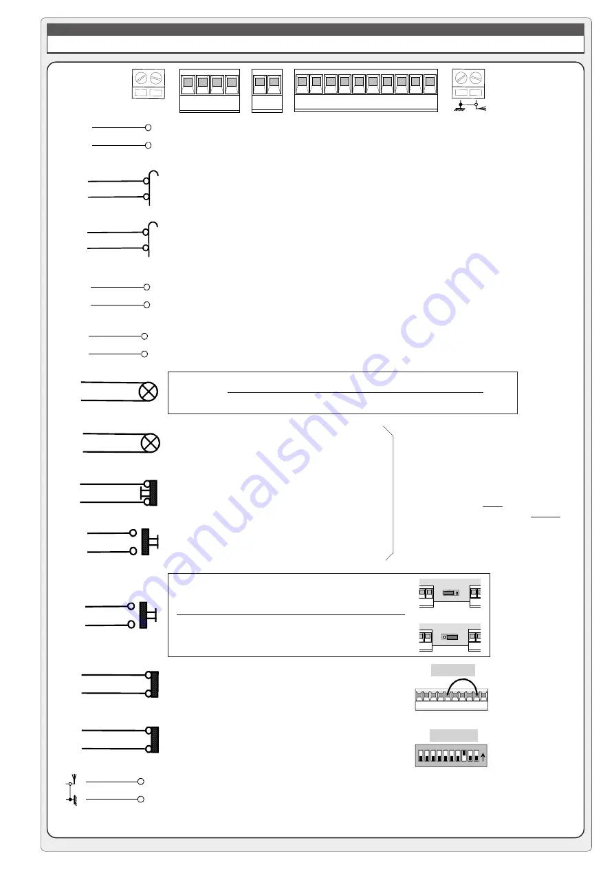
ALLACCIAMENTI & REGOLAZIONI ELETTRONICHE

QUADRO ELETTRICO ZL37B

L1 L2

FA FC F PT

E +10-11 1 2

C1C5

7

3 5

M N

F
FA

F
FC

M
N

24V A.C. motor

Connection limit switch deceleration opens

Connection limit switch deceleration closes

230V A.C. power

Accessory power: 24V A.C. max. 40W

24V output

24V - 3W max. "barrier open" warning light

STOP button (N.C.) 

(see 

selection functions

)

OPEN button (N.O.)

Connector (N.O.) radio and/or pushbutton.
See DIP 2 for command type

Button operation: closure only

Contact (N.C.) for re-opening during closure, if not
used ....

Contact (N.C.) of immediate closure, if not used ....

Antenna connection

L1
L2

10
5

10
E

10
11

1
2

2
3

2
7

2
C5

2
C1

E   10  11 1    2    3   5    7

C

1

  C

5

2-C1


! " # $ % & ' 

ON

dip 8  ON

DIP 3 OFF

DIP 3 ON

during movement (e.g. flashing light)

during movement and in the closed position

7

4

7

4

jumper n°8

To install additional pushbutton arrays,
connect:
- the 

stop

 buttons in serie

- the 

open

 and 

warning light 

in parallel

Summary of Contents for G12000 Series

Page 1: ...Documentazione Tecnica 56 rev 2 0 03 2001 CAME CANCELLI AUTOMATICI 119G56 GB SERIE GARD G12000 CANCELLI AUTOMATICI ROAD BARRIER...

Page 2: ...barrier Description Motorised barrier for control of passages with width of up to 12 m Designed and built entirely by CAME S p A meets UNI 8612 safety standards with IP54 degree of protection Guarant...

Page 3: ...rectangular plates which are assembled as needed 5 RELEASE SYSTEM Manual with PVC handle and cord in self lubricating sheath safety lock 6 HOUSING Load bearing structure in steel profiles and externa...

Page 4: ...base is perfectly level and that the electrical cables for the unit protrude in the area indicated b detach the mounting base from the housing and mount the anchor stays on the base apply grease and...

Page 5: ...f the rear tube 100 mm cut the tube to the correct length and install the end cap fixed length 6200 mm depth of insertion b assemble the barrier bar by sliding the rear tube into the front tube 120 mm...

Page 6: ...ing base c position and mount the fixed support for the barrier bar and make sure it is in perfect longitudinal alignment with the housing g check for misalignment and adjust if necessary then firmly...

Page 7: ...the support alternatively on the left and right until the bar shows signs of raising N B if not all the counterweight plates are used they must be fixed with a hose clamp to avoid possible release dur...

Page 8: ...arged automatically refer to instruction sheet Flashing signal light when bar is in motion Plug in radio receiver Other functions available Automatic closing The automatic closing timer is automatical...

Page 9: ...t STOP button N C see selection functions OPEN button N O Connector N O radio and or pushbutton See DIP 2 for command type Button operation closure only Contact N C for re opening during closure if no...

Page 10: ...vated 2 2 3 funcion 24V output during movement and in the closed position ON OFF activated deactivated 3 3 3 function 24V output during movement ON OFF deactivated activated 3 3 9 9 function total sto...

Page 11: ...LACI N TRIMMERS EINTELLUNG TRIMMERS R GLAGE TRIMMERS TRIMMERS ADJUSTMENT REGOLAZIONE TRIMMERS SENS T C A Trimmer SENS Adjustment of amperometric sensitivity min max Trimmer T C A Adjustment automatic...

Page 12: ...first encoding operation must be carried out whilst keeping the jumpers positioned for channels 1 and 2 as per fig A see fig B for any subsequent settings on different channels T262L M T302L M P1 P2...

Page 13: ...1 P2 CH2 P3 CH3 P4 CH4 1 2 3 4 5 6 7 8 9 10 C P1 P2 P3 P4 T432S set the code to dip switch C and channel to D P1 CH1 and P2 CH2 default setting T432M T312M 1 2 3 4 5 6 7 8 9 10 1 2 3 4 C D P1 P2 P2 CH...

Page 14: ...the lights up of LED sign the code stored Fig 2 IMPORTANT Do not store the code on the circuit card unless the barrier is closed N B If you wish to change the code on your transmitters in the future...

Page 15: ...al board for the pilot motor in the normal CONNECTIONS FOR 2 COMBINED MOTORS CONTROLLED TOGETHER ZL37B CONTROL PANEL 1 On one of the two control panels set Dip 7 to ON in order to select the motor con...

Page 16: ...33 01 46130505 33 01 46130500 CAME GMBH________KORNTAL BEI STUTTGART 49 07 11839590 49 07 118395925 CAME GMBH____________SEEFELD BEI BERLIN 49 03 33988390 49 03 339885508 CAME PL SP ZO O_____________...

Page 17: ...Gate automation equipment must be installed in accordance with all current legislation namely Machinery Directive 98 37 EC and BS EN12453 Important Information BRUNDLE...

Reviews:

Related manuals for G12000 Series